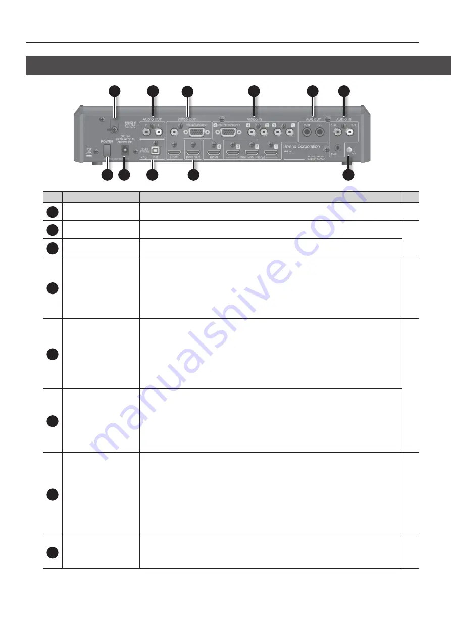
Panel Descriptions
10
No.
Name
Explanation
Page
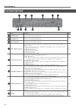
1
[POWER] Switch
This turns the power to the VR-3EX on and off.
2
AC Adaptor Jack
This is for connecting the included AC adaptor.
3
Power Cord Hook
Use this to secure the AC adapter cord in place.
4
Audio Output Connectors
These output the results of audio mixing. Here you connect a video recorder or other recording equipment, or an
amplifier or speakers.
* The VR-3EX has two internal audio buses (the MAIN bus and the AUX bus), and you can select the audio bus to
output for each individual connector.
•
AUDIO OUT Connectors (L, R)
These accept RCA phono type plugs.
•
AUX OUT Connectors (L, R)
These accept 1/4-inch phone type plugs.
5
Video Output Connectors
These output the results of video mixing (main output video).
•
VIDEO output Connector
Here you can connect a video monitor, recording unit, or other device equipped with a composite input connector.
* You can also output the incoming video on video channels 1 through 4 as a four-way split screen.
•
RGB/COMPONENT Output Connector
Here you connect equipment such as a projector or recording unit that is equipped with an analog RGB/compo-
nent input connector.
•
HDMI Output Connector
Here you connect an external display or other device equipped with an HDMI input connector.
6
Video Input Connectors 1–4
These are for inputting video signals from a computer or video devices such as video cameras and DVD players.
•
VIDEO Input Connectors (video channels 1–4)
Here you connect video cameras, DVD players, and other devices equipped with composite output connectors.
•
RGB/COMPONENT Input Connector (video channel 4)
Here you connect a device such as a computer that is equipped with an analog RGB/component output connector.
•
HDMI Input Connectors (video channels 1–4)
Here you connect video cameras and other devices equipped with HDMI output connectors.
* You can specify the video input connector assigned to each individual video channel.
7
Audio Input Connectors 1–7/8
These are for inputting audio signals from video decks, microphones, audio mixers, and other such audio equipment.
You can connect video decks, CD players, microphones, and other devices.
•
AUDIO INPUT (XLR/TRS) Connectors 1–4
These accept XLR and TRS 1/4-inch phone type plugs. Input via XLR/TRS connectors 1 through 4 is assigned to
audio channels 1 through 4.
* You can supply phantom power (+48 V) from the XLR connectors.
•
AUDIO IN 5/6 Connectors (L, R)
These accept RCA phono type plugs. Input via the AUDIO IN 5 and 6 connectors is assigned to audio channel 5 and 6.
•
AUDIO IN 7/8 Connector (L, R)
This accepts a miniature stereo phone plug. Input via the AUDIO IN 7/8 connector is assigned to audio channels 7
and 8.
8
8
USB port
•
This outputs the results of video and audio mixing. You can connect a computer and send video and audio over the
Internet, or record it on the computer.
* You can also output the incoming video on video channels 1 through 4 as a four-way split screen.
•
You can use VR-3EX RCS dedicated software to operate the VR-3EX remotely from a connected computer.
5
4
3
6
4
7
1
2
8
9
10
Rear Panel/Side Panel


