background image

4

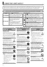
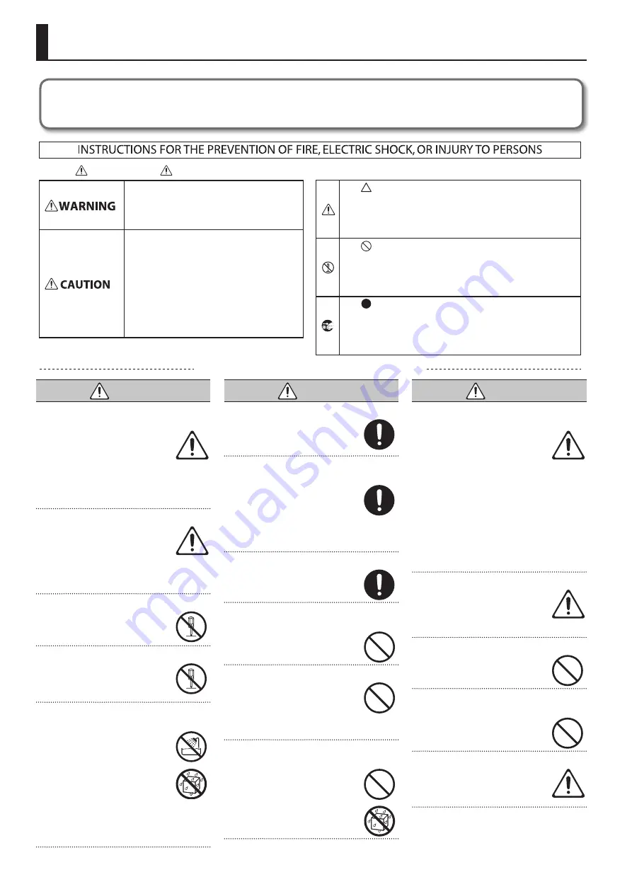
Used for instructions intended to alert the 
user to the risk of injury or material 
damage should the unit be used 
improperly. 
* Material damage refers to damage or 

other adverse effects caused with 
respect to the home and all its 
furnishings, as well to domestic animals 
or pets. 

Used for instructions intended to alert the 
user to the risk of death or severe injury 
should the unit be used improperly. 

The       symbol alerts the user to things that must be 
carried out. The specific thing that must be done is 
indicated by the design contained within the circle. In the 
case of the symbol at left, it means that the power-cord 
plug must be unplugged from the outlet. 

The       symbol alerts the user to important instructions or 
warnings.The specific meaning of the symbol is 
determined by the design contained within the triangle. In 
the case of the symbol at left, it is used for general 
cautions, warnings, or alerts to danger. 

The       symbol alerts the user to items that must never be 
carried out (are forbidden). The specific thing that must 
not be done is indicated by the design contained within 
the circle. In the case of the symbol at left, it means that 
the unit must never be disassembled. 

About       WARNING and       CAUTION Notices

About the Symbols

ALWAYS OBSERVE THE FOLLOWING

USING THE UNIT SAFELY

 WARNING

To completely turn off power to the unit, pull out 

the plug from the outlet

Even with the power switch turned off, this 
unit is not completely separated from its 
main source of power. When the power 
needs to be completely turned off, turn off 
the power switch on the unit, then pull out the plug 
from the outlet. For this reason, the outlet into which 
you choose to connect the power cord’s plug should 
be one that is within easy reach and readily accessible.

Concerning the Auto Off function

The power to this unit will be turned 
off automatically after a predetermined 
amount of time has passed since its 
buttons or controls were operated (Auto 
Off function). If you do not want the power to be 
turned off automatically, disengage the Auto Off 
function (p. 44).

Do not disassemble or modify by yourself

Do not carry out anything unless you are 
instructed to do so in the owner’s manual. 
Otherwise, you risk causing malfunction.

Do not repair or replace parts by yourself

Refer all servicing to your retailer, the 
nearest Roland Service Center, or an 
authorized Roland distributor, as listed on 
the “Information.”

Do not use or store in the following types of 

locations

• 

Subject to temperature extremes (e.g., 
direct sunlight in an enclosed vehicle, 
near a heating duct, on top of heat-
generating equipment); or are

• 

Damp (e.g., baths, washrooms, on wet 
floors); or are

• 

Exposed to steam or smoke; or are

• 

Subject to salt exposure; or are

• 

Exposed to rain; or are

• 

Dusty or sandy; or are

• 

Subject to high levels of vibration and shakiness.

 WARNING

Do not place in an unstable location

Otherwise, you risk injury as the result of 
the unit toppling over or dropping down.

Use only the supplied AC adaptor and the correct 

voltage

Be sure to use only the AC adaptor 
supplied with the unit. Also, make sure the 
line voltage at the installation matches the 
input voltage specified on the AC adaptor’s 
body. Other AC adaptors may use a different polarity, 
or be designed for a different voltage, so their use 
could result in damage, malfunction, or electric shock.

Use only the supplied power cord

Use only the attached power cord. Also, 
the supplied power cord must not be used 
with any other device.

Do not bend the power cord or place heavy objects 

on it

Otherwise, fire or electric shock may result.

Avoid extended use at high volume

Use of the unit at high volume for 
extended periods of time may cause 
hearing loss. If you ever experience any 
hearing loss or ringing in the ears, you 
should immediately stop using the unit 
and consult a specialized physician.

Do not allow foreign objects or liquids to enter 

unit; never place containers with liquid on unit

Do not place containers containing liquid 
(e.g., flower vases) on this product. Never 
allow foreign objects (e.g., flammable 
objects, coins, wires) or liquids (e.g., water 
or juice) to enter this product. Doing so 
may cause short circuits, faulty operation, 
or other malfunctions.

 WARNING

Turn off the unit if an abnormality or malfunction 

occurs

Immediately turn the unit off, remove the 
AC adaptor from the outlet, and request 
servicing by your retailer, the nearest 
Roland Service Center, or an authorized 
Roland distributor, as listed on the “Information” when:

• 

The AC adaptor or the power cord has been 
damaged; or

• 

If smoke or unusual odor occurs; or

• 

Objects have fallen into, or liquid has been spilled 
onto the unit; or

• 

The unit has been exposed to rain (or otherwise has 
become wet); or

• 

The unit does not appear to operate normally or 
exhibits a marked change in performance.

Be cautious to protect children from injury

Always make sure that an adult is on hand 
to provide supervision and guidance when 
using the unit in places where children 
are present, or when a child will be using 
the unit.

Do not drop or subject to strong impact

Otherwise, you risk causing damage or 
malfunction.

Do not share an outlet with an unreasonable 

number of other devices

Otherwise, you risk overheating or fire.

Do not use overseas

Before using the unit in overseas, consult 
with your retailer, the nearest Roland 
Service Center, or an authorized Roland 
distributor, as listed on the “Information.”

Before using this unit, carefully read the sections entitled “USING THE UNIT SAFELY” and  “IMPORTANT NOTES” (p. 6). These sections provide 

important information concerning the proper operation of the unit. Additionally, in order to feel assured that you have gained a good grasp of every 

feature of your new unit, read Owner’s manual in its entirety. This manual should be saved and kept on hand as a convenient reference.

Summary of Contents for VR-3EX

Page 1: ...l of the unit via MIDI It also describes MIDI Implementations detailed documentation of MIDI messages To obtain the PDF manual 1 Enter the following URL in your computer http www rolandsystemsgroup ne...

Page 2: ...d by the letter E or by the safety earth symbol or coloured GREEN or GREEN AND YELLOW The wire which is coloured BLUE must be connected to the terminal which is marked with the letter N or coloured BL...

Page 3: ...this manual uses the following conventions Text enclosed in square brackets indicates the name of a button or a knob such as the SETUP button VALUE knob Text enclosed in angle brackets indicates text...

Page 4: ...shakiness WARNING Do not place in an unstable location Otherwise you risk injury as the result of the unit toppling over or dropping down Use only the supplied AC adaptor and the correct voltage Be s...

Page 5: ...r connect disconnect a power plug if your hands are wet Otherwise you could receive an electric shock Disconnect all cords cables before moving the unit Before moving the unit disconnect the power plu...

Page 6: ...we carry out repairs in some cases such as when the memory section is physically damaged restoration of the stored content may be impossible Roland assumes no liability concerning the restoration of...

Page 7: ...ing the Video 27 Compositing Using Picture in Picture PinP 27 Compositing Using Split SPLIT 28 Compositing Four Video Streams on a Single Screen QUAD 29 Compositing Using Luminance Key Chroma Key 30 A...

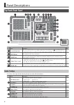
Page 8: ...cted correctly p 17 p 18 p 24 5 PHONES Jacks You can use these to connect standard type 1 4 inch and mini stereo headphones You can use both at the same time p 15 Audio Section This section is for mix...

Page 9: ...picture gradually disappears the next video is overlaid and progressively grows more visible WIPE Button In this transition the original video is broken into by the next video p 24 17 COMPOSITION Butt...

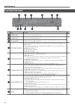
Page 10: ...video channels 1 4 Here you connect video cameras DVD players and other devices equipped with composite output connectors RGB COMPONENT Input Connector video channel 4 Here you connect a device such...

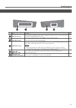
Page 11: ...off The unit has separate switches for audio channels 1 2 and audio channels 3 4 so you can set these individually NOTE Always turn the phantom power OFF when connecting any device other than condense...

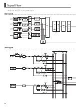
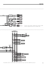
Page 12: ...aler 480p 576p Frame Sync Composite HDMI INPUT 1 INPUT 2 INPUT 3 RGB Component Composite HDMI INPUT 4 Audio signals 48V FOLLOW EQ 3Band FOLLOW FOLLOW INPUT BUS HPF EQ GATE COMP DELAY DELAY GATE COMP H...

Page 13: ...tput 3 frames from Input 4 to Output Internal Processing 480 59 94p when set to NTSC 576 50p when set to PAL MAIN L R AUX L R L R SOLO L R OUTPUT BUS DELAY DELAY HDMI VIDEO OUT HDMI PVW OUT PHONES OUT...

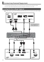
Page 14: ...d specify the video input connector for inputting video channels 1 through 4 p 20 Analog RGB output connector Video cameras DVD players etc Video source equipment Computer HDMI outputconnector Compone...

Page 15: ...to dynamic microphones audio playback devices or other devices that don t require such power Be sure to check the specifications of any microphone you intend to use by referring to the manual that cam...

Page 16: ...device by the computer Connecting the AC Adaptor Place the AC adaptor so the side with the indicator see illustra tion faces upwards and the side with textual information faces downwards The indicato...

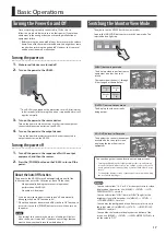
Page 17: ...f by the Auto Off function to restart first press the POWER button to return it then turn on the power NOTE Any settings that you are in the process of editing will be lost when the power is turned of...

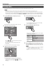
Page 18: ...can also choose an icon by turning and pressing the VALUE knob A list of menu items for the selected category is displayed 3 Touch the screen to select a setting item The selected setting item is dis...

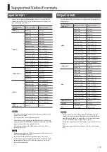
Page 19: ...VR 3EX is carried out at 480p when set to NTSC or 576p when set to PAL This means that an interlaced signal that is input is internally converted to a progressive signal by theVR 3EX The picture might...

Page 20: ...I and RGB COMPONENT output connectors is set at AUTO the setting for automatic detection If you want to specify an output format of your choosing change the setting to match the setting on the device...

Page 21: ...RAST This adjusts the contrast OUTPUT BRIGHTNESS This adjusts the brightness OUTPUT COLOR This adjusts the color OUTPUT COLOR SPACE This sets the color space system for represent ing colors in video o...

Page 22: ...splay position in the vertical direction H SIZE This adjusts the size in the horizontal direction V SIZE This adjusts the size in the vertical direction CONTRAST This adjusts the contrast BRIGHTNESS T...

Page 23: ...p 20 to check the status of HDCP support of connected equipment An HDCP icon is displayed according to the status of HDCP support HDCP icon HDCP icon Connector HDCP support status HDMI input Copyrigh...

Page 24: ...wipe has been selected as the transition effect you can set a video transition time in a range of 0 0 to 4 0 seconds Adjust so that the video changes with the timing you want When the setting is 0 0...

Page 25: ...automatic switching feature is turned off MEMO You can set a video transition interval in a range of 1 to 120 seconds Use MENU g SETUP g AUTO SCAN TIME to make the setting 5 Press the MENU button twic...

Page 26: ...e OUTPUT knob to its center position Lighted The indicator stops flashing and lights up steadily and output starts MEMO You can adjust the level of the fade color Use MENU g VIDEO OUTPUT g OUTFADE WHI...

Page 27: ...ion effects Use the TRANSITION knob to adjust the fade time While compositing of the video is in progress the video switches with cuts regardless of the selected transition effect 1 Press the MONITOR...

Page 28: ...vertical size of the inset screen BORDER This adjusts the width of the border for the inset screen BORDER COLOR This sets the color of the border for the inset screen SHADOW This adjusts the length o...

Page 29: ...ettings for the items described below Setting item Explanation A CENTER This adjusts the center position of the video displayed on side A B CENTER This adjusts the center position of the video display...

Page 30: ...de time You can set the extraction color for luminance keying and the degree of edge blur of the picture displayed in the foreground Use MENU g KEY to make the settings Setting item Explanation LUMI K...

Page 31: ...blue or green background onto a different background video Green or Blue CHROMA NOTE Chroma key composition sometimes leaves color or small artifacts at the edges of the extracted video but this is n...

Page 32: ...t channels 1 4 is displayed on the monitor 7 Touch the channel screen you want to make the background video A red border is displayed around the selected channel screen 8 Press the KEY button The KEY...

Page 33: ...gradations in brightness COLOR PASS This produces monochrome video with a specific color remaining MULTI This divides the video vertically or horizontally to produce multiple screens OFF This assigns...

Page 34: ...put sensitivity Adjust so that the SIG PEAK indicator above the GAIN knob briefly lights up in red when the audio from the source equipment is at its highest volume level The SIG PEAK indicator lights...

Page 35: ...ing HDMI audio turn the HDMI knobs all the way counterclockwise to lower the volume level completely You can check the level meter at the bottom of the screen to determine whether the volume has been...

Page 36: ...s boosts or attenuates the middle band EQ LO This boosts or attenuates the low band FREQ HI MID LO This adjusts the center frequency for changing sound quality Q MID This adjusts the width of the freq...

Page 37: ...This suppresses high frequency distortion and adjusts the sound to have sustained tones MASTER MID This suppresses midrange distortion and adjusts the sound to have distinct tones MASTER LO This supp...

Page 38: ...nc Normally because video processing takes more time than audio processing the video is output later than the audio resulting in video and audio that are out of sync On the VR 3EX you can delay output...

Page 39: ...Video and Audio Lip sync p 38 Assigning an Audio Bus to Audio Output Connectors 1 Press the MAIN SETUP button The setup screen for main audio output is displayed 2 Touch BUS SELECT The BUS SELECT scre...

Page 40: ...AUDIO FOLLOW The AUDIO FOLLOW screen is displayed 4 Touch the matrix chart and turn the VALUE knob to make the settings for Audio Follow Video channel Input audio For each video channel specify the in...

Page 41: ...eo channels 1 through 4 Output Signals Signals in the following video and audio formats are output from the VR 3EX s USB port Video Audio When set to NTSC When set to PAL 720 x 480 pixels Motion JPEG...

Page 42: ...s p 43 Recalling 1 Press the MENU button to display the menu screen 2 Touch MEMORY The MEMORY menu is displayed 3 Touch LOAD SETTING 4 Turn the VALUE knob to select the memory number 1 through 4 conta...

Page 43: ...a popup dialog box appears 6 In the popup dialog box click Save To quit without backing up click Cancel A dialog box for saving the file appears 7 Specify the destination for saving the file and a fi...

Page 44: ...splayed 3 Touch AUTO OFF 4 Turn the VALUE knob to set the Auto Off function on or off Value Explanation ON The Auto Off function is turned on Power is turned off automatically OFF The Auto Off functio...

Page 45: ...ent video signal p 19 NTSC standard Frame rate at 59 94 PAL standard Frame rate at 50 1 Press the MENU button to display the menu screen 2 Touch SETUP The SETUP menu is displayed 3 Touch NTSC PAL 4 Tu...

Page 46: ...correctly Set the extraction color white or black to match the background color of the logo or text p 30 Has the KEY LEVEL knob been turned in the correct direction When compositing using luminance k...

Page 47: ...f the inset screen at a fixed aspect ratio H SIZE 1 220 This adjusts the horizontal size of the inset screen V SIZE 1 220 This adjusts the vertical size of the inset screen BORDER 0 3 15 This adjusts...

Page 48: ...destination for saving LOAD SETTING 1 4 This sets the memory number to recall MANUAL MODE ON OFF When set to ON the settings in memory are recalled while maintain ing the settings for the current con...

Page 49: ...e time until compression starts when audio exceeding the threshold is input RELEASE 30 500 5000 ms This adjusts the length of time until compression ends after audio falls below the threshold HPF ON O...

Page 50: ...is adjusts the center frequency when changing the sound quality in the high band EQ MID 15 0 15 dB This boosts or attenuates the middle band FREQ 20 0 Hz 2 50 KHz 10 0 KHz This adjusts the center freq...

Page 51: ...the degree of application of the noise suppressor ENHANCER 0 127 This adjusts the degree of application of the enhancer MASTER HIGH 0 127 This suppresses high frequency distortion and adjusts the sou...

Page 52: ...lide01 26 Stretch01 26 Normal Wipe 01 99 Wipe01 Wipe02 Wipe03 Wipe04 Wipe05 Wipe06 Wipe07 Wipe08 Wipe09 Wipe10 Wipe11 Wipe12 Wipe13 Wipe14 Wipe15 Wipe16 Wipe17 Wipe18 Wipe19 Wipe20 Wipe21 Wipe22 Wipe2...

Page 53: ...e18 SWipe19 SWipe20 SWipe21 SWipe22 SWipe23 SWipe24 SWipe25 SWipe26 SWipe27 SWipe28 SWipe29 SWipe30 SWipe31 SWipe32 SWipe33 SWipe34 SWipe35 SWipe36 SWipe37 SWipe38 SWipe39 SWipe40 SWipe41 SWipe42 SWip...

Page 54: ...ide11 Slide12 Slide13 Slide14 Slide15 Slide16 Slide18 Slide19 Slide20 Slide09 Slide Sequence Type Slide21 26 Slide17 Slide21 Slide22 Slide23 Slide24 Slide25 Slide26 1 A B 2 B A 1 A B 2 B A 1 A B 2 B A...

Page 55: ...When a non interlaced format is selected RGB signal is output from the RGB COMPONENT connector The refresh rates of RGB format is 60 Hz when set to NTSC 75 Hz when set to PAL excluding 1600 x 1200 and...

Page 56: ...hms Headphones Output Signal Level 25 mW 25 mW Output Impedance 10 ohms Display Graphic Color LCD 320 x 240 dots touch panel Video Effects Transition Cut Mix 3 patterns Wipe 250 patterns VIDEO FX Stro...

Page 57: ...OUT SETUP button 20 INPUT button 17 Input formats 19 22 Input mode 17 Input sensitivity 34 Inset screen 27 28 Interlinking audio follow 40 INTERNAL MIC knob 35 Internal microphones 35 K KEY button 31...

Page 58: ...dicator 34 SOFT EDGE 29 SOLO 38 SOLO CLEAR 38 Sound position 34 SPLIT 28 SPLIT button 29 Streaming 41 Supported OS 16 T THRESHOLD 36 TIME 37 Timing Lip sync 38 TRANSITION buttons 24 Transition effects...

Page 59: ...equipment and receiver Connect the equipment into an outlet on a circuit different from that to which the receiver is connected Consult the dealer or an experienced radio TV technician for help This d...

Page 60: ...5 1 0 0 0 3 8 7 8 3 0 1 For EU Countries For China...

Reviews: