background image

2


5

Roland is an either registered trademark or trademark of Roland Corporation in the United States and/or other countries.


5

Company names and product names appearing in this document are registered trademarks or trademarks of their respective owners.

Summary of Contents for VR-50HD MK II

Page 1: ...round terminal Before connecting the ground cord or any external devices you must minimize the volume of all devices and turn off the power of all devices in order to prevent faulty operation or malfu...

Page 2: ...gistered trademark or trademark of Roland Corporation in the United States and or other countries 5 5 Company names and product names appearing in this document are registered trademarks or trademarks...

Page 3: ...lance 25 Correcting a Time Difference Between Video and Audio Delay 25 Applying Effects to Input Audio 26 Applying Effects to Output Audio 27 Interlinking Audio Output to Video Switching Audio Follow...

Page 4: ...function is on this indicates the output status of the audio p 27 Lit green Audio is not being output Lit red Audio is being output Blinking red Audio is being faded in out Audio follow is a function...

Page 5: ...ected button is lit red 20 VIDEO INPUT SELECT 1 4 STILL buttons p 13 Select the video that is output an input video 1 4 or the still image STILL The selected button is lit INPUT ASSIGN button p 10 Sho...

Page 6: ...SLEEVE GND 3 COLD 2 HOT 1 GND 3 COLD About phantom power You can supply phantom power 48 V from the AUDIO IN 1 4 jacks XLR Turn on phantom power when you re using a condenser microphone that requires...

Page 7: ...on you can reset the selected menu item whose background is red to its default value If you continue holding the buttons all menu items in the same screen will return to their default values 7If the v...

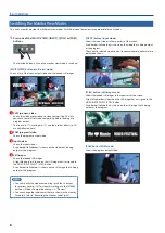
Page 8: ...light blue border is shown on the still image that is assigned to the VIDEO INPUT SELECT STILL button A red border tally border is shown on the still image that is being output as the program MEMO 5 Y...

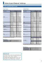
Page 9: ...50i 1080 59 94p 1080 50p 1024 x 768 60Hz 1024 x 768 75Hz 1280 x 720 60Hz 1280 x 720 60Hz 1280 x 800 60Hz 1280 x 800 75Hz 1280 x 1024 60Hz 1280 x 1024 75Hz 1400 x 1050 60Hz 1400 x 1050 60Hz 1920 x 1080...

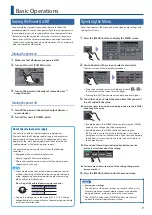
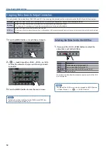
Page 10: ...Stream 0 Resolution p 32 AssigningVideo Sources Here s how to assign the video sources being input from the video input connectors to the VIDEO INPUT SELECT 1 4 buttons 1 Press the INPUT ASSIGN butto...

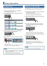
Page 11: ...o output restrictions If HDCP is on restrictions apply to the video audio output Video and audio respectively are output only from the following connectors Source Connectors available for output Video...

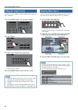
Page 12: ...m output such as when you want a specific input video to be a fixed output 1 Press the MENU button0touch Video Output 2 0touch Output Bus PGM PVW or AUX to select the video bus that you want to assign...

Page 13: ...t mode you can switch the video by touching an input video in the screen Outputting a Loaded Still Image A still image loaded into this unit can be assigned to the VIDEO INPUT SELECT STILL button and...

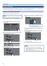
Page 14: ...Source PGM or AUX and specify the video from which you want to capture Value Explanation PGM PGM bus video AUX AUX bus video 3 Touch Output Capture Still 4 Touch a box to specify the save destination...

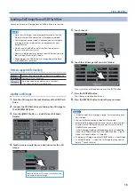
Page 15: ...he root directory of the USB flash drive 2 Connect the USB flash drive containing the still image to the USB MEMORY port 3 Press the MENU button0touch Video Still Load Delete 4 Touch a box to specify...

Page 16: ...l audio detection resumes 3 Touch Video Follows Audio to turn it ON The video follow audio function turns on 4 Press the MENU button to close the menu screen MEMO 5 The MIC 5 and MIC 7 settings are va...

Page 17: ...l image of your choice This is convenient when you want to output a user logo such as the logo of a company or a product name 1 In advance load a still image into this unit as described by the followi...

Page 18: ...e the video PinP KEY layer PinP luminance chroma key PinP luminance key or chroma key is used to composite the video PinP and luminance chroma key can be used simultaneously Program video Background v...

Page 19: ...MEMO If mix or wipe are selected as the video transition effect the setting of the TIME knob specifies the time over which the inset screen appears or disappears Making detailed settings for the inse...

Page 20: ...Background Chroma Key p 22 If you want to use only PinP compositing disable the key compositing setting Use the PinP KEY SOURCE button0 Detail 0 0 and set KEY to OFF 5 If mix or wipe are selected as...

Page 21: ...xplanation Lumi White Makes white portions transparent according to brightness Lumi Black Makes black portions transparent according to brightness 5 Press the EXIT button to return to the previous men...

Page 22: ...djust the degree of key removal Select the layer to preview 7 Press the MENU button to close the menu screen 8 Press the PinP KEY button The PinP KEY button is lit red and the composited result is sen...

Page 23: ...touch the Type button to select the key type Value Explanation Lumi White Makes white portions transparent according to brightness Lumi Black Makes black portions transparent according to brightness C...

Page 24: ...DIO IN 1 audio as an example NOTE Turning the GAIN knobs may produce a popping noise or cause momentary audio drop out but this is not a malfunction 1 Position the channel 1 audio fader near the 0 dB...

Page 25: ...to adjust the volume of the output The MAIN level meter will light yellow at the appropriate volume Red Excessive Yellow Appropriate Green Insufficient Correcting aTime Difference Between Video and A...

Page 26: ...istening 7Equalizer This is a four band parametric equalizer It lets you shape the character of the sound by boosting or cutting four frequency regions The width of the frequency regions can be change...

Page 27: ...shape the character of the sound by boosting or cutting each of the 15 frequency regions into which the sound is divided Interlinking Audio Output toVideo Switching Audio Follow Here s how the audio...

Page 28: ...e the volume level of an emcee microphone raise the weight level of that audio to emphasize it and lower the weight level for other audio 5 On audio to which Auto Mixing is applied setting the weight...

Page 29: ...1 Press the MAIN SELECT button to display the Audio Output screen 2 Touch 0touch AUX 1 or AUX 2 for the jacks to which you want to assign the AUX bus 3 Press the MAIN SELECT button to close the menu s...

Page 30: ...stering Camera Settings in a Preset Up to eight sets of settings such as camera position and focus can be registered as presets A registered preset can be recalled when needed Presets are saved in the...

Page 31: ...ntrol 0 touch All Camera Recall to turn it ON 2 In Camera Preset touch the preset number that you want to recall Presets are recalled from all cameras simultaneously 3 Press the MENU button to close t...

Page 32: ...s unit to output video audio to your computer 6 On your computer verify the input from this unit Start software that supports the USB video class and audio class and verify the video and audio that ar...

Page 33: ...button to close the menu screen MEMO 5 About the fader knob setting values With the factory settings when you recall a memory or start up the unit the values reflect the current position of the fader...

Page 34: ...ished entering the name press the ENTER button The current settings are saved to the USB flash drive as a file 5 Press the MENU button to close the menu screen Overwrite saving 1 Press the MENU button...

Page 35: ...button 4 To format the USB flash drive press the ENTER button Formatting is executed 5 Press the MENU button to close the menu screen Renaming the Monitor Label You can rename the labels that are show...

Page 36: ...y previously specified content any settings saved in memory p 33 and the still image p 14 saved in the unit will all be lost 5 Never turn off the power or remove the USB flash drive while the message...

Page 37: ...ecifies the position from which the audio sent to the AUX 2 bus is taken Pre Send the audio before it is adjusted by the fader pre fader Post Send the audio after it passes through the fader post fade...

Page 38: ...frequency band when boosting or attenuating low midrange band Low 15 0 15dB Boosts or attenuates the low band Frequency 20Hz 100Hz 2 0kHz Adjusts the center frequency when changing the tone quality i...

Page 39: ...the delay time of the audio Delays the output of the audio by the specified time Pan 1 Left L49 L01 Center R01 R49 Right Adjusts the stereo position pan Mono 2 Converts the input audio from stereo to...

Page 40: ...es the high midrange band Frequency 20 0Hz 2 0kHz 20 0kHz Adjusts the center frequency when changing the tone quality in the high midrange band Q 0 3 1 0 16 0 Adjusts the width of the frequency band w...

Page 41: ...f 10 0dB Adjusts the output volume Solo OFF ON Turns the solo function on off Only the audio for which this is ON is heard in the headphones Mute OFF ON Turns the mute function on off If this is ON th...

Page 42: ...the specified threshold level is compressed This reduces the difference between the maximum volume and minimum volume making the audio more comfortable for listening Lim This is a limiter Compresses t...

Page 43: ...B 2 5k 15 0 0 0 15 0dB 4k 15 0 0 0 15 0dB 6 3k 15 0 0 0 15 0dB 10k 15 0 0 0 15 0dB 16k 15 0 0 0 15 0dB Flat Sets the equalizer settings to flat 0 0 dB AUX 1 7 Adjusts the audio of the AUX 1 bus AUX 1...

Page 44: ...udio input from any mic If this is OFF the last selected video continues to be output Time 0 4 0 30 0sec Specifies the time after the video has switched until audio detection resumes 8 The MIC 5 and M...

Page 45: ...3 Adjusts the green level Blue 64 0 63 Adjusts the blue level Color Space Auto RGB 0 255 RGB 16 235 YCC SD YCC HD Specifies the color space Flicker Filter OFF ON If this is ON flickering is reduced ED...

Page 46: ...justs the zoom ratio Position H 1920 0 1920 Adjusts the position in the horizontal direction Position V 1080 0 1080 Adjusts the position in the vertical direction 11 The valid range of setting values...

Page 47: ...value Explanation Format Touch to access the Format Select screen 480 576i 4 3 480 576i 16 9 480 576p 4 3 480 576p 16 9 720p 1080i 1080p 1024 x 768 1280 x 720 1280 x 800 1280 x 1024 1400 x 1050 1920 x...

Page 48: ...M RGB 0 255 RGB 16 235 YCC 4 4 4 YCC 4 2 2 Specifies the color space that is output from each HDMI OUT connector HDMI AUX HDMI MULTI VIEW Input Assign Screen Press the INPUT ASSIGN button or MENU butt...

Page 49: ...are in common with the settings of the Video Input screen For details on the menu items refer to Video Input 1 4 Screen p 45 PinP KEY Source screen Menu item Value bold text default value Explanation...

Page 50: ...s the red level of the border color Green 0 128 255 Adjusts the green level of the border color Blue 0 128 255 Adjusts the blue level of the border color Width 0 128 255 Adjusts the width of the borde...

Page 51: ...s the blue level of the border color Width 0 5 63 Adjusts the width of the border KEY Menu item Value bold text default value Explanation KEY OFF ON Enables ON or disables OFF the key settings Type Sp...

Page 52: ...aded when this unit starts Save the same file in the root directory of the USB flash drive and start this unit with the USB flash drive connected Delete Deletes the still image that is loaded into the...

Page 53: ...ke it light red and then touch a Memory No number to save the settings to a memory The following settings are common to the unit one set for the entire unit and therefore are not saved in memory 5 5 M...

Page 54: ...k Panel Lock Enables or disables locking of the operating panel When the operating panel is locked the MENU button is lit OFF Unlocks the operating panel Part Buttons and knobs other than the followin...

Page 55: ...preset Touch Store to make it light red and then touch a Camera Preset number to register the settings in a preset Presets are saved in the camera itself Camera Preset 1 8 Recall presets Setup Displa...

Page 56: ...ess a screen where you can enter a login name Enter the log in name needed to connect with the camera Password If the Protocol is JVC touch this to access a screen where you can enter a password Enter...

Page 57: ...Displays the subnet mask Subnet Mask Displays the MAC address 2 Press the MENU button to close the menu screen RS 232C Interface RS 232C connector pin layout Pin assignments 1 2 3 4 5 6 7 8 9 DB 9 ty...

Page 58: ...Inf dB 127 10 dB Recall memory stxMEM a ack a 0 Memory 1 7 Memory 8 Select video for AUX bus stxAUX a ack a 0 INPUT 1 1 INPUT 2 2 INPUT 3 3 INPUT 4 4 STILL 4 PinP 5 PinP KEY 6 PGM Select source video...

Page 59: ...s stxPGM a stxQPG a a 0 INPUT 1 1 INPUT 2 2 INPUT 3 3 INPUT 4 4 STILL This is enabled when the unit receives the command stxCPG 1 Error detected stxTRS a stxERR a a 0 syntax error The received command...

Page 60: ...e cases it may exhibit a missing pixel or a pixel that remains constantly lighted This is not a malfunction Can t connect via USB 3 0 Video is jerky Could you be connecting via an extension cable or a...

Page 61: ...orms to CEA 861 E or VESA DMT Version 1 0 Revision 11 HDMI HDMI OUT MULTI VIEW 1080 59 94p Conforms to CEA 861 E or VESA DMT Version 1 0 Revision 11 Component RGB COMPONENT IN RGB COMPONENT OUT 2 480...

Page 62: ...Analog gain Min 60 dBu MAIN fader 0 0 dB Only channel 1 fader 0 0 dB Analog gain Max Input 150 terminate Output connectors AUDIO OUT AUX 1 L R 100 dBu All faders Min 98 dBu MAIN fader 0 0 dB Only chan...

Page 63: ...63 Appendices Dimensions 437 325 132 Unit mm...

Page 64: ...PGM HDMI MULTI VIEW OSD LCD USB Memory OUTPUT CAPTURE AUX AUX Bus source USER LOGO HDMI AUX RGB COMPONENT PGM RGB COMPONENT AUX HDMI PGM SDI AUX SDI PGM USB STREAMING OUTPUT Still Memory 1 4 VIDEO FO...

Page 65: ...2 COMP LIMITER 4 BAND EQ METER R L AUX 1 LEVEL AUX 2 LEVEL TONE TEST SIG PEAK MUTE MUTE SOLO SOLO SOLO HPF DELAY GATE COMP 4 BAND EQ FX Voice changer Anti feedback SOLO REVERB LEVEL AUX2 SEND AUX1 SE...

Reviews: