6
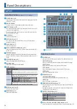
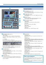
Panel Descriptions
1
2
3
4
5
6
7
8
9
10
11
12
NOTE
Do not block the cooling-fan intake and exhaust ports on
the side panels. If the cooling-fan intake and exhaust ports
are blocked, the internal temperatures may rise, causing
malfunctions due to excessive heat.
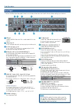
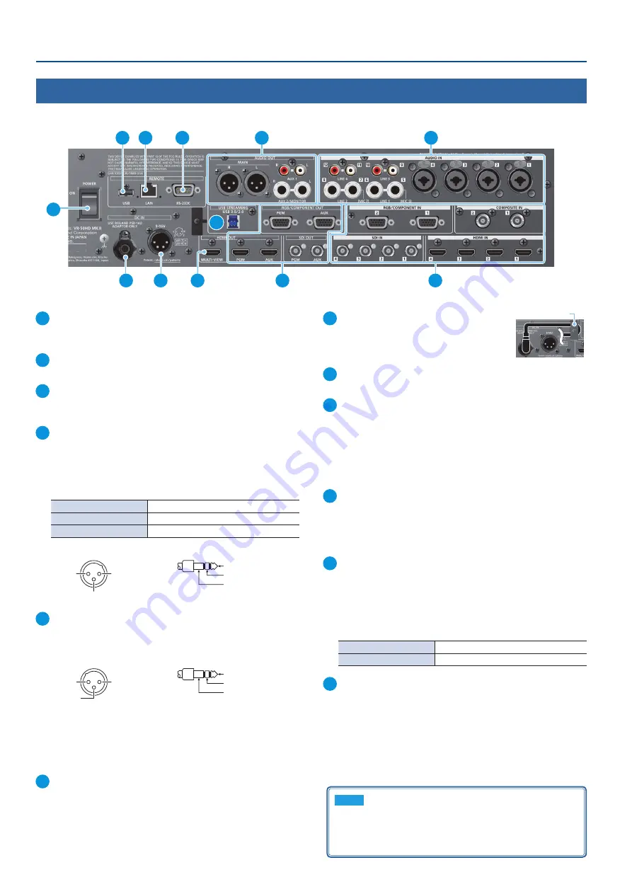
Rear Panel
* To prevent malfunction and equipment failure, always turn down the volume, and turn off all the units before making any connections.
1
USB port
Connect a USB flash drive here. This is used to update the system
program.
2
LAN port (p. 57)
Lets you remotely control this unit by using terminal software, etc.
3
RS-232C connector (p. 57)
You can connect this to a computer equipped with an RS-232C
connector, and remotely control this unit.
4
MAIN jacks, AUX 1 jacks, AUX 2/MONITOR jacks
These jacks output audio. Choose the jacks that are appropriate
for the connected devices.
For each jack, you can change the audio bus (MAIN, AUX 1, AUX 2)
that is assigned for output from that jack (p. 12). With the factory
settings, the bus assignments are as follows.
MAIN jacks
MAIN bus
AUX 1 jacks
AUX 1 bus
AUX 2/MONITOR jacks
AUX 2 bus
* Pin assignment of MAIN (XLR) jacks, AUX 2/MONITOR (TRS) jacks
1: GND
2: HOT
TIP: HOT
RING: COLD
SLEEVE: GND
3: COLD
2: HOT
1: GND
3: COLD
1: GND
2: HOT
TIP: HOT
RING: COLD
SLEEVE: GND
3: COLD
2: HOT
1: GND
3: COLD
5
AUDIO IN 1–4 jacks, LINE 1–4 jacks, MIC 5/7 jacks
These jacks input audio. Choose the jacks that are appropriate for
the connected devices.
* Pin assignment of AUDIO IN 1–4 (TRS/XLR) jacks, LINE 1–2 (TRS) jacks
1: GND
2: HOT
TIP: HOT
RING: COLD
SLEEVE: GND
3: COLD
2: HOT
1: GND
3: COLD
1: GND
2: HOT
TIP: HOT
RING: COLD
SLEEVE: GND
3: COLD
2: HOT
1: GND
3: COLD
*
About phantom power
You can supply phantom power (+48 V) from the AUDIO IN 1–4
jacks (XLR). Turn on phantom power when you’re using a condenser
microphone that requires phantom power.
Use the [MENU] button
0
Audio <1>–<4>
0
set “+48V” to “ON.”
6
[POWER] switch (p. 7)
Turns the power on/off.
7
AC adaptor jack
Connect the included AC adaptor to this jack.
* Use the cord hook to secure the cord of the AC
adaptor as shown in the illustration.
8
External power supply connector (p. 7)
Connect the external power supply here.
9
USB STREAMING port (p. 32)
Outputs the audio and video to your computer.
* If you are outputting HD video via USB, connect this to a USB 3.0 port
of your computer.
* If you connect via an extension cable or a USB hub, the computer
might not recognize this unit. We recommend that you connect this
unit directly to your computer.
10
MULTI-VIEW connector
Outputs a list of the input/output video and the loaded still
images. The screen layout is the same as when this unit’s monitor
is in multi-view mode (p. 8).
* The output format fixed at 1080/60p.
11
PGM connectors, AUX connectors
(RGB/COMPONENT OUT, HDMI OUT, SDI OUT)
These connectors output video. Choose the connectors that are
appropriate for the connected devices.
For each connector, you can change the video bus (PGM, PVW,
AUX) that is assigned for output from that connector (p. 12). With
the factory settings, the bus assignments are as follows.
PGM connectors
PGM bus (program video)
AUX connectors
AUX bus
12
RGB/COMPONENT IN 1–2 connectors
COMPOSITE IN 1–2 connectors
SDI IN 1–4 connectors, HDMI IN 1–4 connectors
These connectors input video. Choose the connectors that are
appropriate for the connected devices.
The input format is automatically recognized.
Cord hook

