3-38
18
17
[ ]
SERVICE MENU
MOTOR MENU
SERVO LOCK
S: 3
MOTOR MENU
SERVO LOCK
[ ]
[ ]
SERVO LOCK
S: * 1688
SERVO LOCK
S: 1688
[ENTER]
15
MENU
SERVICE MENU
+
MENU
16
Right Frame
Panel Board
When fixing the Panel
Cover, fi x the sensor with
the sensor cable and the
ribbon cable to the Panel
Board.
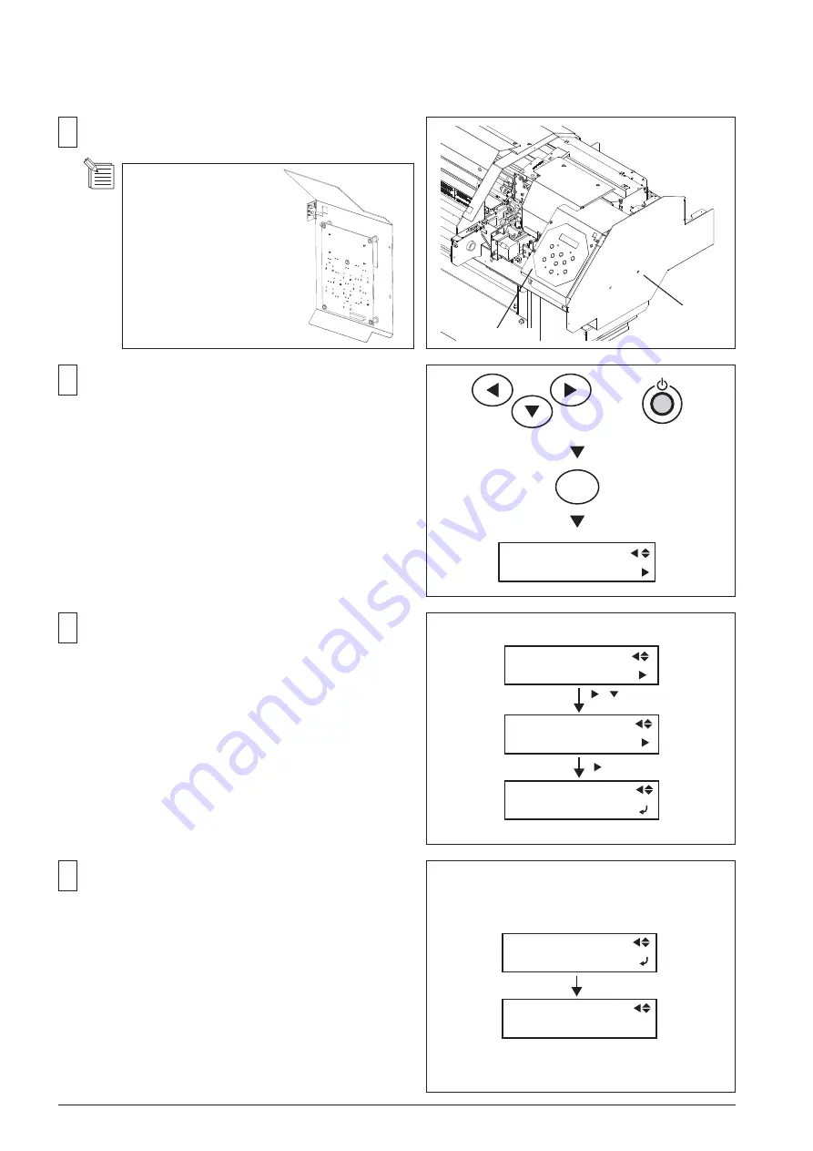
Perform the SERVO LOCK CHECK.
After turning on the Main Power SW, turn on the Sub Power
SW while pressing the left, right and down keys to enter the
Service Mode.
Fix the Right Frame and Panel Cover.
In [MOTOR MENU]>[SERVO LOCK] menu, select [S].
Move the Head Carriage left and right by hand and make
sure the value on the LCD changes depending on the head
position.
Press the [ENTER] key to excite the motor.
Check the Head Carriage can not be moved easily by hand
and the value on the LCD doesn't change.
Summary of Contents for VS-300
Page 49: ...2 4 MAIN BOARD_Arrangement Diagram Soldering Side ...
Page 60: ...2 15 SERVO BOARD_Arrangement Diagram Soldering Side ...
Page 65: ...2 20 2 4 CARRIAGE BOARD CARRIAGE BOARD_Arrangement Diagram Component Side ...
Page 68: ...2 23 2 5 SUB BOARD SUB BOARD_Arrangement Diagram Component Side ...


