background image

User M anual of Network Video  Recorder 


21 

2.1


Starting Up and Shutting Down the NVR 

Purpose: 

Proper startup and shutdown procedures are crucial  to expanding  the life of the NVR. 

Before you start: 

Check  that  the  voltage  of  the  extra  power  supply  is  the  same  with  the  NVR’s  requirement,  and  the  ground 

connection is working properly. 

Starting up the NVR: 

Steps: 

1.


Check the power supply is plugged into an electrical  outlet. It is HIGHLY recommended  that an 

Uninterruptible Power Supply (UPS) be used in conjunction with the device.   

2.


Turn on the power switch on the rear panel. 

3.


After startup, the Power LED indicator turns on. A splash screen with the status of the HDD appears on the 

monitor. The row of icons at the bottom of the screen shows the HDD status. ‘X’ means that the HDD is not 

installed or cannot be detected. 

S hutting down the NVR 

Steps: 

1.


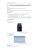
Enter the Shutdown menu.


M enu > Shutdown 


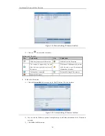
Figure 2. 1


Shutdown  Menu 


2.


Click the 

S hutdown

 button. 

3.


Click the 

Yes

 button. 

4.


Turn off the power switch on the rear panel when the attention pops up . 


Figure 2. 2


Shutdown  Attention 


Rebooting the NVR 

In the Shutdown menu, you can also reboot the NVR. 

Summary of Contents for UD.6L0202D1275A02

Page 1: ...Network Video Recorder User Manual UD 6L0202D1275A02 ...

Page 2: ... accept any interference received including interference that may cause undesired operation EU Conformity Statement This product and if applicable the supplied accessories too are marked with CE and comply therefore with the applicable harmonized European standards listed under theLow Voltage Directive 2006 95 EC the EMC Directive 2004 108 EC 2002 96 EC WEEE directive Products marked with this sym...

Page 3: ... is properly secured to a rack or shelf Major shocks or jolts to the unit as a result of dropping it may cause damage to the sensitive electronics within the unit Use thedevice in conjunction with an UPS if possible Power down the unit before connecting and disconnecting accessories and peripherals A factory recommended HDD should be used for this device Improper use or replacement of the battery ...

Page 4: ...User Manualof Network Video Recorder 4 Thank you for purchasing our product If there is any question or request please do not hesitate to contact dealer ...

Page 5: ...agement Up to 2 SATAhard disks can be connected Each disk with a maximum of 4TB storage capacity 8 network disks 8 NAS disks or 7 NAS disks 1 IP SAN disk can be connected Support S M A R T and bad sector detection HDD group management Support HDD standby function HDD property redundancy read only read write R W HDD quota management different capacity can be assigned to different channel Recording ...

Page 6: ...arching Manually triggering and clearing alarms Import and export of device configuration information Network Functions 1 self adaptive 10M 100M 1000M network interface Up to 8 independent network interfaces with built in switch function are provided IPv6 is supported TCP IP protocol PPPoE DHCP DNS DDNS NTP SADP SMTP SNMP NFS and iSCSI are supported TCP UDP and RTP for unicast Auto Manualport mapp...

Page 7: ...nualof Network Video Recorder 7 Embedded WEB server Development Scalability SDK for Windows and Linux system Source code of application software for demo Development support and training for application system ...

Page 8: ...e View 35 3 2 Operations in Live View Mode 36 3 2 1 Using the Mouse in Live View 36 3 2 2 Quick Setting Toolbar in Live View Mode 37 3 3 Adjusting Live View Settings 39 3 4 User Logout 41 Chapter4 PTZ Controls 42 4 1 Configuring PTZ Settings 43 4 2 Setting PTZ Presets Patrols Patterns 44 4 2 1 Customizing Presets 44 4 2 2 Calling Presets 44 4 2 3 Customizing Patrols 46 4 2 4 Calling Patrols 47 4 2...

Page 9: ...8 Alarm Settings 98 8 1 Setting Motion Detection Alarm 99 8 2 Setting Sensor Alarms 101 8 3 Detecting Video Loss Alarm 104 8 4 Detecting Video TamperingAlarm 106 8 5 Handling Exceptions Alarm 108 8 6 SettingAlarm ResponseActions 109 8 7 Triggering or Clearing Alarm Output Manually 111 Chapter9 Network Settings 112 9 1 Configuring General Settings 113 9 2 ConfiguringAdvanced Settings 114 9 2 1 Conf...

Page 10: ...t and Maintenance 150 12 1 Viewing System Information 151 12 1 1 Viewing Device Information 151 12 1 2 Viewing Camera Information 151 12 1 3 Viewing Record Information 151 12 1 4 ViewingAlarm Information 152 12 1 5 Viewing Network Information 152 12 1 6 Viewing HDD Information 153 12 2 Searching Export Log Files 153 12 3 Importing Exporting Configuration Files 157 12 4 Upgrading System 158 12 4 1 ...

Page 11: ...User Manualof Network Video Recorder 11 ...

Page 12: ...User Manualof Network Video Recorder 12 Chapter 1 Introduction ...

Page 13: ...links red when data is being read from or written to HDD Tx Rx TX RX indictor blinks yellow when network connection is functioning properly 2 USB Interface Universal Serial Bus USB ports for additional devices such as USB mouse and USB Hard Disk Drive HDD 1 2 IR Remote Control Operations The NVR may also be controlled with the included IR remote control shown in Figure 1 2 Batteries 2 AAA must be ...

Page 14: ... to delete the character in front of the cursor On checkbox fields pressing the button will tick thecheckbox In PTZ Controlmode thebutton adjusts the iris of the camera In Playback mode it can be used to generate video clips for backup Enter exit the folder of USB device 5 A Button Adjust focus in the PTZ Controlmenu It is also used to switch between input methods upper and lowercase alphabet symb...

Page 15: ...channels In PTZ controlmode it can control the movement of thePTZ camera ENTER Button Confirm selection in any of the menu modes It can also be used to tick checkbox fields In Playback mode it can be used to play or pause thevideo In single frame Playback mode pressing the button will advance the video by a single frame 13 PTZ Button In Auto switch mode it can be used to stop start auto switch 14 ...

Page 16: ... Press the ENTER button on the remote If the Status indicator on thefront panel turns blue the remote control is operating properly If theStatus indicator does not turn blue and there is still no responsefrom the remote please check the following 1 Batteries are installed correctly and the polarities of the batteries are not reversed 2 Batteries are fresh and not out of charge 3 IR receiver is not...

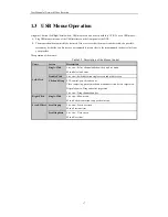
Page 17: ...ider The operation of the mouse Table 1 3 Description of the Mouse Control Name Action Description Left Click Single Click Live view Select channel and show the quick set menu Menu Select and enter Double Click Live view Switch between single screen and multi screen Click and Drag PTZ control pan tilt and zoom Video tampering privacy mask and motion detection Select target area Digital zoom in Dra...

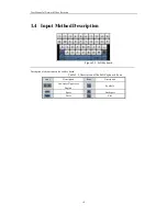
Page 18: ...Input Method Description Figure 1 3 Soft Keyboard Description of the buttons on the soft keyboard Table 1 4 Description of the Soft Keyboard Icons Icons Description Icons Description Lowercase Uppercase English Symbols Space Backspace Enter Exit ...

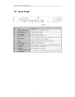
Page 19: ...USB Interface Universal Serial Bus USB ports for additional devices such as USB mouse and USB Hard Disk Drive HDD 6 GND Ground needs to be connected when NVR starts up 7 HDMI Interface HDMI video output connector 8 VGA Output DB9 connector for VGA output Display local video output and menu 9 Audio In RCA connector for voice talk input 10 Audio Out RCA connector for audio output 11 Network interfac...

Page 20: ...User Manualof Network Video Recorder 20 Chapter 2 Getting Started ...

Page 21: ...tiblePower Supply UPS be used in conjunction with the device 2 Turn on the power switch on the rear panel 3 After startup thePower LED indicator turns on A splash screen with the status of the HDD appears on the monitor The row of icons at the bottomof the screen shows the HDD status X means that theHDD is not installed or cannot be detected Shutting down the NVR Steps 1 Enter the Shutdown menu Me...

Page 22: ...User Manualof Network Video Recorder 22 Steps 1 Enter the Shutdown menu by clicking Menu Shutdown 2 Click the Logout button to lock the NVR or the Reboot button to reboot the NVR ...

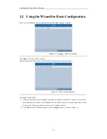
Page 23: ... starts once theNVR has loaded as shown in Figure below Figure 2 4 Start Wizard Interface Operating the Setup Wizard 1 The Setup Wizard can walk you through some important settings of the NVR If you don t want to use the Setup Wizard at that moment click the Exit button You can also choose to use the Setup Wizard next time by leaving the Start wizard when thedevice starts checkbox checked 2 Click ...

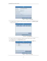
Page 24: ...rd check the New Admin Password checkbox Enter the new password and confirm the password in the given fields 5 Click the Next button to enter thedate and time settings window as shown in Figure 2 6 Figure 2 6 Date and Time Settings 6 After the time settings click Next button which takes you back to the Network Setup Wizard window as shown in Figure 2 7 ...

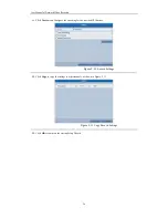
Page 25: ...heHDD Management window shown in Figure 2 8 Figure 2 8 HDD Management 8 To initialize the HDD click the Init button Initialization removes all the data saved in theHDD 9 Click Next button to enter the Adding IP Camera interface 10 Click Search to find online IP Camera Select theIP camera to be added and click the Add button Figure 2 9 Search for IP Cameras ...

Page 26: ... Next button Configure the recording for the searched IP Cameras Figure 2 10 Record Settings 12 Click Copy to copy thesettings to other channels as shown in Figure 2 11 Figure 2 11 Copy Record Settings 13 Click OK to complete the startup Setup Wizard ...

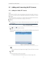
Page 27: ...k Traffic and Chapter Configuring Network Detection OPTION 1 Steps 1 Move the mouse to the top of the screen or right click the mouse when you in the live view mode to show the right click menu Figure 2 12 Right click Menu 2 Select Auto or Manual on your demand Auto The device will add the detected IP cameras or encoders automatically by the default user name and password of administrator Figure 2...

Page 28: ...con to get the live view of the camera The camera is disconnected you can click the icon to get the exception information of camera The camera is connected Advanced settings of the camera Delete the IP camera 2 To add other IP cameras 1 Click the Custom Add button to pop up theAdd IP Camera Custom interface Figure 2 15 Custom Adding IP Camera Interface 2 You can edit the IP address protocol manage...

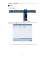
Page 29: ...Camera Figure 2 16 Main Menu 2 Repeat the step 1 and 2 of adding IP cameras manually to add the camera Figure 2 17 IP Camera Management Interface 3 For the encoders with multiple channels only check the checkbox of Channel No in the pop up window as shown in thefollowing figure and click OK to finish adding ...

Page 30: ...sic information of the camera lists in the page you can configure the basic setting of theIP cameras Steps 1 Click the icon to edit the parameters you can edit the IP address protocoland other parameters Figure 2 19 Edit the Parameters 2 Click OK to save the settings and exit the editing interface To edit advanced parameters 1 Drag the horizontalscroll bar to theright most side and click the icon ...

Page 31: ...guration of the Camera 3 Click Apply to save the settings and click OK to exit the interface Configuring the customized protocols Purpose To connect thenetwork cameras which are not configured with thestandard protocols you can configure the customized protocols for them Steps 1 Click the Protocol button in theAdd IP Camera Custom interface to enter the protocol management interface ...

Page 32: ...he customprotocol Enable Substream If the network camera does not support sub stream or the sub stream is not needed leave the checkbox empty Type The network camera adopting customprotocolmust support gettingstream through standard RTSP TransferProtocol Select the transfer protocolfor the custom protocol Port Set the port number for thecustom protocol Path Set the resource path for the custom pro...

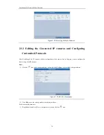
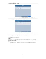
Page 33: ...ras And the PoE interface supports the Plug and Play function Example As for 4 PoE NVR when you want to connect 1 online camera and connect 3 network cameras via PoE interfaces you must disable 1 PoE interface in the Edit IP camera panel To add Cameras for NVR supporting PoE function Before you start Connect the network cameras via the PoE interfaces Steps 1 Enter the Camera Management interface M...

Page 34: ...er 9 1 Configuring General Settings for detailed information Figure 2 25 Edit IP Camera Interface Plug and Play Manual You can disable the PoE interface by selecting the manual while the current channel can be used as a normal channel and the parameters can also be edited Figure 2 26 Edit IP Camera Interface Manual 3 Click the Apply button to finish adding Chapter 3 Live View ...

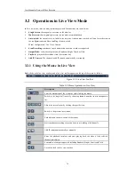
Page 35: ... there are icons at the right top of the screen for each channel showing the status of the record and alarm in the channel so that you can know whether the channel is recorded or whether there are alarms occur as soon as possible Table 3 1 Description of Live View Icons Icons Description Alarm video loss tampering motion detection or sensor alarm Record manual record schedule record motion detecti...

Page 36: ...mera The shortcut to add IP camera automatically or manually 3 2 1 Using the Mouse in Live View Right click on the live view window and a live view toolbar appears on thetop of thescreen as follows Figure 3 9 Live View Toolbar Table 3 2 Mouse Operation in Live View Name Description Enter the main menu of the systemby right clicking themouse Switch to the single full screen by choosing channel numb...

Page 37: ...le click the mouse in the corresponding screen Figure 3 10 Quick Setting Toolbar Table 3 3 Description of Quick Setting Toolbar Icons Icons Description Icons Description Icons Description Enable Disable Record Instant Playback Mute Audio on PTZ Control Digital Zoom Image Settings Live View Strategy Close Instant Playback only shows the record in last five minutes If no record is found it means the...

Page 38: ...lected to enter the Image Settings menu You can set theimage parameters like brightness contrast saturation and hue Figure 3 12 Image Settings Customize Live View Strategy can be selected to set strategy including Real time Balanced Fluency Figure 3 13 Live View Strategy ...

Page 39: ...settings available in this menu include Video Output Interface Designates theoutput to configure the settings for Only VGA HDMI is selectable by default Live View Mode Designates thedisplay mode to be used for Live View Dwell Time Thetime in seconds to dwell between switching of channels when enabling auto switch in Live View Enable Audio Output Enables disables audio output for the selected video...

Page 40: ...View mode in 2 Select the small window and double click on the channel number to display thechannel on thewindow You can click button to start live view for all thechannels and click to stop all the live view 3 Click the Apply button to save the setting ...

Page 41: ...de and if you want to do some operation you need to enter user name and password tog in again Steps 1 Enter the Shutdown menu Menu Shutdown Figure 3 16 Shutdown 2 Click Logout After you have logged out the system menu operation on the screen is invalid It is required to input a user name and password to unlock thesystem ...

Page 42: ...User Manualof Network Video Recorder 42 Chapter 4 PTZ Controls ...

Page 43: ...amera Steps 1 Enter the PTZ Settings interface Menu Camera PTZ Figure 4 1 PTZ General 2 Choose the camera for PTZ setting in the Camera dropdown list 3 Enter the parameters of the PTZ camera All the parameters should be exactly thesame as the PTZ camera parameters Example If the PTZ camera uses the protocolof DRAGON you should select DRAGON in the PTZ Protocol field 4 Click Apply button to save th...

Page 44: ...o when an event takes place Steps 1 Enter the PTZ Controlinterface Menu Camera PTZ MoreSettings Figure 4 2 PTZ More Settings 2 Use thedirectional button to wheel the camera to the location where you want to set preset 3 Click the round icon before Save Preset 4 Click the preset number to save thepreset Repeat the steps2 4 to save more presets If thenumber of the presets you want to save is more th...

Page 45: ...rface Menu Camera PTZ MoreSettings 2 Check theround icon of Call Preset Figure 4 4 PTZ Call Preset 3 Choose the preset number Call preset in live view mode Steps 1 Press the PTZ button on the front panel or click the PTZ Controlicon in the quick setting bar to enter the PTZ settingmenu in live view mode Figure 4 5 PTZ Toolbar 2 Choose Camera in the list on the menu 3 Double click the preset in the...

Page 46: ...rol 3 Select the under Patrol option box to add key points for the patrol Figure 4 6 PTZ Add Key Point 4 Configure key point parameters such as the key point No duration of stayingfor one key point and speed of patrol The key point is corresponding to thepreset The Key Point No determines the order at which the PTZ will follow while cycling through the patrol The Duration refers to the time span t...

Page 47: ...es the PTZ to move according thepredefined patrolpath Calling patrol in the PTZ setting interface Steps 1 In the PTZ settinginterface Menu Camera PTZ MoreSettings 2 Select the patrolnumber and then click to call thepatrol 3 Click to stop it Calling patrol in live view mode Steps 1 Press PTZ control on thefront panel or on theremote or click PTZ Controlicon on thequick setting toolbar to show the P...

Page 48: ...ePTZ movement according to thepredefined path Steps 1 Enter the PTZ Controlinterface Menu Camera PTZ MoreSettings 2 Choose pattern number in the option box Figure 4 10 PTZ Pattern 3 Click and use your mouse to drag the image or click theeight directional buttons in the control box under the image to move the PTZ camera The movement of the PTZ is recorded as the pattern 4 Click to save thepattern ...

Page 49: ...Settings 2 Select the pattern number 3 Click then thePTZ moves according to thepattern 4 Click to stop it Figure 4 11 PTZ Calling Pattern Call pattern in live view mode Steps 1 In the live view mode press PTZ controlon thefront panel or on theremote control or click PTZ Control icon on thequick setting toolbar 2 And then choose Pattern on the control bar 3 Double click thepattern or select the pat...

Page 50: ... no mouse is connected the icon will be displayed in the lower left corner of the window indicating that this camera is in PTZ control mode Figure 4 13 PTZ Toolbar Table 4 1 Description of the PTZ toolbar icons Icon Description Icon Description Icon Description Direction button and auto cycle button Zoom Focus Iris Zoom Focus Iris Speed bar of PTZ movement Light on off Wiper on off 3D positioning ...

Page 51: ...User Manualof Network Video Recorder 51 Chapter 5 Record Settings ...

Page 52: ...DD General Figure 5 1 HDD General 2 Check thestorage mode of theHDD 1 Click Advanced to check thestorage mode of theHDD 2 If the HDD mode is Quota please set the maximum record capacity For detailed information see Chapter Configuring Quota Mode 3 If the HDD mode is Group you should set the HDD group For detailed information see Chapter Configuring HDD Group for Recording Figure 5 2 HDD Advanced S...

Page 53: ...time for thefile should be determined by the capacity of theHDD Redundant Record Enabling redundant record means you save the record in the redundant HDD See Chapter Configuring Redundant Recording Record Audio Check thecheckbox to enable or disable audio recording 2 Click Apply to save the settings The redundant record is to decide whether you want the camera to save the record files in the redun...

Page 54: ...ule Figure 5 6 Record Schedule 2 Choose the camera you want to configure 3 Select the check box after the Enable Schedule item 4 Click Edit button or click on the color icon under the edit button and draw the schedule line on the panel Edit the schedule I In the message box you can choose the day to which you want to set schedule Figure 5 7 Recording Schedule Interface You can click the button to ...

Page 55: ... schedule steps to schedule recording for other days in the week If the schedule can also be applied to other days click Copy Figure 5 9 Copy Schedule to Other Days IV Click OK to save setting and back to upper level menu V Click Apply in theRecord Schedule interface to save thesettings Draw the schedule Click on the color icons you can choose the schedule typeas continuous or event Figure 5 10 Dr...

Page 56: ...e 5 11 Descriptions of the color icons Click the Apply button to validate the settings If the settings can also be used to other channels click Copy and then choose the channel to which you want to copy Figure 5 12 Copy Schedule to Other Channels ...

Page 57: ...enter and so on In this chapter you can follow the steps to schedule a record which triggered by the detected motion Steps 1 Enter the Motion Detection interface Menu Camera Motion Figure 5 13 Motion Detection 2 Configure Motion Detection 1 Choose camera you want to configure 2 Check thecheckbox after Enable Motion Detection 3 Drag and draw the area for motion detection by mouse If you want to set...

Page 58: ... you want themotion detection event to trigger recording 6 Click Apply to save the settings 7 Click OK to back to the upper level menu 8 Exit the Motion Detection menu 3 Edit the Motion Detection Record Schedule For the detailed information of schedule configuration see Chapter Configuring Record Schedule ...

Page 59: ...ecording Steps 1 Enter theAlarm setting interface Menu Configuration Alarm Figure 5 16 Alarm Settings 2 Click the Alarm Input tab Figure 5 17 Alarm Settings Alarm Input 1 Select Alarm Input number and configure alarm parameters 2 Choose N O normally open or N C normally closed for alarm type 3 Check thecheckbox of Enable 4 Click Settings ...

Page 60: ...o back to the upper level menu Repeat the above steps to configure other alarm input parameters If the settings can also be applied to other alarm inputs click Copy and choose the alarm input number Figure 5 19 Copy Alarm Input 3 Edit the Alarm triggered record in the Record Schedule setting interface For the detailed information of schedule configuration see Chapter Configuring Record Schedule ...

Page 61: ...tings interface Menu Manual Or press theREC button on the remote control Figure 5 20 Manual Record 2 Enabling Manual Record 1 Select Record on theleft bar 2 Click the status button beforecamera number to change to 3 Disable manual record Click the status button to change to Note Green icon means that the channel is configured the record schedule After rebooting all the manual records enabled are c...

Page 62: ...day Settings 2 Enable Edit Holiday schedule 1 Click to enter the Edit interface Figure 5 22 Edit Holiday Settings 2 Check thecheckbox after Enable Holiday 3 Select Modefrom thedropdown list There are three different modes for the date format to configure holiday schedule 4 Set the start and end date 5 Click Apply to save settings 6 Click OK to exit the Edit interface 3 Enter Record Schedule settin...

Page 63: ...click to enter theLocal HDD Settings interface 1 Set the HDD property to Redundancy Figure 5 24 HDD General Editing 2 Click Apply to save the settings 3 Click OK to back to the upper level menu You must set the Storage mode in the HDD advanced settings to Group before you set the HDD property to Redundant For detailed information please refer to Chapter 10 3 Managing HDD Group There should be at l...

Page 64: ... Recorder 64 2 Select Camera you want to configure in thedrop down list 3 Check thecheckbox of Redundant Record 4 Click Apply to save settings and back to the upper level menu Repeat the above steps for configuring other channels ...

Page 65: ... Check whether the storage mode of the HDD is Group If not set it to Group For detailed information please refer to Chapter 12 4 Managing HDD Group 3 Select General in the left bar Click to enter editing interface Figure 5 28 Local HDD Settings 4 Configuring HDD group 1 Choose a group number for the HDD group 2 Click Apply and then in the pop up message box click Yes to save your settings 3 Click ...

Page 66: ...oup 1 Select Advanced on theleft bar 2 Choose Group number in thedropdown list of Record on HDD Group 3 Check thechannels you want to save in this group 4 Click Apply to save settings After having configured the HDD groups you can configure the recording settings following the procedure provided in Chapter 5 2 5 7 ...

Page 67: ...you want to investigate by checking the checkbox to 3 Configure therecord type file typestart end time 4 Click Search to show theresults Figure 5 30 Playback Search Result 5 Protect the record files 1 Find the record files you want to protect and then click the icon which will turn to indicating that the file is locked The record files of which the recording is still not completed cannot be locked...

Page 68: ... 3 Set the HDD property to Read only 4 Click OK to save settings and back to the upper level menu You cannot save any files in a Read only HDD If you want to save files in the HDD change the property to R W If there is only one HDD and is set to Read only the NVR can t record any files Only live view mode is available If you set the HDD to Read only when the NVR is saving files in it then the file...

Page 69: ...User Manualof Network Video Recorder 69 Chapter 6 Playback ...

Page 70: ...his channel will be played back Figure 6 1 Instant Playback Interface OPTION 2 1 Enter the Playback interface Right click on the live view window and the live view toolbar appears at the top of the screen Then click the icon on the live view toolbar to enter thePlayback interface Under multi screen live view mode the recorded files of the top left channel will be played back Pressing numerical but...

Page 71: ...herecord Table 6 1 Detailed Explanation of Playback Toolbar Button Operation Button Operation Button Operation Button Operation Mute Audio on Start Stop clipping Add default tag Add customized tag Tag management Digital Zoom Smart Search Pause Play reverse Pause Play Stop 30s reverse 30s forward Slow forward Fast forward Previous day Next day Scaling up down time bar Process bar Full screen Exit N...

Page 72: ...k and channel switch are supported Steps 1 Enter playback interface Menu Playback 2 Check thecheckbox of channel s in thechannel list and then double click to select a date on the calendar Figure 6 4 Playback Calendar If there are record files for that camera in that day in the calendar the icon for that day is displayed as Otherwiseit is displayed as In the Playback interface The toolbar in the b...

Page 73: ...peration Button Operation Button Operation Mute Audio on Start Stop clipping Add default tag Add customized tag Tag management Digital Zoom Smart Search Pause Play reverse Pause Play Stop 30s reverse 30s forward Slow forward Fast forward Previous day Next day Scaling up down time bar Process bar Full Screen Exit Normal playback Playback progress bar use the mouse to click any point of the progress...

Page 74: ...otion detection Steps 1 Enter the Playback interface Menu Playback 2 Select the Event in the drop down list on the top left side 3 Select Alarm Input or Motion as theevent type edit the Start time and End time Figure 6 7 Alarm Input Search Interface Figure 6 8 Motion Search Interface 4 Click Search button to get the search result information You may refer to the right side bar for the result ...

Page 75: ...ent is set to trigger the recording of multiple channels clicking the will pop up the Synch Playback interface You can select thechannels to play back synchronously You can click theBack button to back to the search interface Playback interface The toolbar in the bottompart of Playback interface can be used to control playing process Figure 6 10 Interface of Playback by Event ...

Page 76: ...own time bar Process bar Full Screen Exit Event playback Playback progress bar use the mouse to click any point of the progress bar or drag the progress bar to locate special frames 6 1 4 Playing Back by Tag Purpose Video tag allows you to record related information like people and location of a certain time point during playback You are also allowed to use video tag s to search for record files a...

Page 77: ...s can be added to a single video file 3 Tag management Click button to check edit and delete tag s Figure 6 13 Tag Management Interface Steps 1 Select the Tag from the drop down list in thePlayback interface 2 Choose channels edit start time and end time and then click Search to enter Search Result interface You can enter keyword in thetextbox to search the tag on your command ...

Page 78: ...re 6 14 Video Search by Tag 3 Click button to play back the file You can click theBack button to back to the search interface Pre play and post play can be configured Figure 6 15 Interface of Playback by Tag Figure 6 16 Toolbar of Playback by Tag ...

Page 79: ... Slow forward Fast forward Previous tag Next tag Scaling up down time bar Process bar Full Screen Exit Tag playback Playback progress bar use the mouse to click any point of the progress bar or drag the progress bar to locate special frames 6 1 5 Playing Back by System Logs Purpose Play back record file s associated with channels after searching systemlogs Steps 1 Enter Log Information interface M...

Page 80: ...ord file and click button to enter Playback interface If there is no record file at the time point of the log the message box No result found will pop up Figure 6 18 Result of System Log Search 4 Playback interface The toolbar in the bottompart of Playback interface can be used to control playing process ...

Page 81: ...p and play back files in the external devices Steps 1 Enter Tag Search interface Menu Playback 2 Select the External File in the drop down list on the top left side The files are listed in the right side list You can click the Refresh button to refresh the file list 3 Select and click the button to play back it Figure 6 20 Interface of External File Playback ...

Page 82: ...e motion detection event easily and accurately in the playback progress bar you are allowed to analyze a certain area scene dynamically and to get all of the related motion detection events that occurred in this area The smart search function varies according to the camera connected to theNVR Before you start 1 Log in thenetwork camera by the web browser and enable the Dynamic Analysis for Motion ...

Page 83: ... s You can click button to set the full screen as target searching area Multi area and full screen searching modes are supported Figure 6 23 Draw Area of Smart Search 4 Click the icon to start thesmart search and themotion events occurred in the defined area will be marked as on the time bar The hidden list of record files display when moving themouse to the right of the playback interface ...

Page 84: ...ation Button Operation Button Operation Mute Audio on Start Stop clipping Add default tag Add customized tag Tag management Digital Zoom Smart Search Pause Play reverse Pause Play Stop 30s reverse 30s forward Slow forward Fast forward Previous result Next result Scaling up down time bar Process bar Full Screen Exit Normal playback Playback progress bar use the mouse to click any point of the progr...

Page 85: ...al zoominterface 6 2 4 Reverse Playback of Multi channel Purpose You can play back record files of multi channel reversely Up to 8 ch with 4CIF resolution simultaneous reverse playback is supported up to 4 ch with 720P resolution simultaneous reverse playback is supported up to 2 ch with 1080P resolution and up to 1 ch with 5MP resolution reverse playback is supported Steps 1 Enter Playback interf...

Page 86: ...User Manualof Network Video Recorder 86 Figure 6 27 4 ch Synchronous Playback Interface 3 Click to play back therecord files reversely ...

Page 87: ...User Manualof Network Video Recorder 87 Chapter 7 Backup ...

Page 88: ...t search condition and click Search button to enter the search result interface Figure 7 1 Normal Video Search for Backup 3 Select record files you want to back up Click to play the record file if you want to check it Check thecheckbox before the record files you want to back up The sizeof the currently selected files is displayed in the lower left corner of thewindow Figure 7 2 Result of Normal V...

Page 89: ...backup device and click button to play it Click Format button to format thebackup device Figure 7 3 Export by Normal Video Search using USB Flash Drive USB writers and DVD R W Click Erase button if you want to erase the files from a re writable CD DVD There must be a re writable CD DVD when you make this operation Figure 7 4 Export by Normal Video Search using USB Writer 5 Select the backup device...

Page 90: ...hoose the record file in Export interface and click button to check it Figure 7 7 Checkup of Export Result using USB Flash Drive 7 1 2 Backing up by Event Search Purpose Back up event related record files using USB devices USB flash drives USB HDDs USB writer or SATA writer Quick Backup and Normal Backup are supported Steps 1 Enter Export interface Menu Export Event 1 Select Alarm Input from the d...

Page 91: ...ackup 2 Click Search button to enter the Search Result interface Figure 7 9 Result of Event Search 3 Select record files to export Clicking Quick Export button will export record files of all channels triggered by the selected alarm input Clicking Details button willtake you to the interface with detailed information of all channels triggered by the selected alarm input Figure 7 10 Event Details I...

Page 92: ... also format USB flash drive or USB HDDs via thedevice Figure 7 11 Export by Event Using USB Flash Drive 5 Select the backup device from the drop down list click thebutton Export And then select to export the video and log files or the player to the backup device Click OKto confirm Figure 1 1 Export Selection Stay in theExporting interface until all record files are exported with pop up messagebox...

Page 93: ...ly during Playback using USB devices USB flash drives USB HDDs USB writer or SATA writer Steps 1 Enter Playback interface Please refer to Chapter 6 1 Playing Back Record Files Figure 7 14 Interface of Playback by Time 2 During playback use buttons and in the playback toolbar to start or stop clipping record file s 3 Quit Playback interface after finishing clipping and you will then be prompted to ...

Page 94: ... USB device is not recognized Click the Refresh button Reconnect device Check for compatibility from vendor You can also format USB flash drive or USB HDDs via thedevice Figure 7 16 Export Video Clips Using USB Flash Drive 6 Select the backup device from the drop down list click thebutton Export And then select to export the video and log files or the player to the backup device Click OKto confirm...

Page 95: ... Result Using USB Flash Drive 7 2 Managing Backup Devices Steps 1 Enter Search Result interface of record files Menu Export Normal Set search condition and click Search button to enter Search Result interface At least one channel shall be selected Figure 7 20 Normal Video Search for Backup 2 Select record files you want to back up ...

Page 96: ...lick the Refresh button Reconnect device Check for compatibility from vendor USB flash drives and USB HDDs Click New Folder button if you want to create a new folder in the backup device Select a record file or folder in the backup device and click button if you want to delete it Select a record file in thebackup device and click button to play it Click Format button to format thebackup device Fig...

Page 97: ...anualof Network Video Recorder 97 Click Erase button if you want to erase the files from a re writable CD DVD There must be a re writable CD DVD when you make this operation Figure 7 23 USB Writer Management ...

Page 98: ...User Manualof Network Video Recorder 98 Chapter 8 Alarm Settings ...

Page 99: ...t sensitivity Click button and set alarm responseactions 3 Click TriggerChannel tab and select one or more channels which will start to record or become full screen monitoring when motion alarm is triggered and click Apply to save thesettings Figure 8 2 Set Trigger Camera of Motion Detection 4 Set up arming schedule of the channel 1 Select Arming Schedule tab to set the arming schedule of handling...

Page 100: ...o set up alarm response actions of motion alarm please refer to Chapter Setting Alarm Response Actions Repeat the above steps to set up arming schedule of other days of a week You can also use Copy button to copy an arming schedule to other days 6 Click the OKbutton to complete the motion detection settings of thechannel ...

Page 101: ... to set up its alarm responseactions Figure 8 5 Alarm Input Setup Interface 3 Select Trigger Channel tab and select one or more channels which will start to record or become full screen monitoring when an external alarm is input 4 Select Arming Schedule tab to set thechannel s arming schedule Choose one day of a week and Max eight time periods can be set within each day Time periods shall not be r...

Page 102: ... parameters and click OK to complete the settings of the alarm input Please check whether the PTZ or speed dome supports PTZ linkage One alarm input can trigger presets patrolor pattern of more than one channel But presets patrols and patterns are exclusive Figure 8 7 Set PTZ Linking of Alarm Input 7 If you want to set handling action of another alarm input repeat theabove steps or just copy theab...

Page 103: ...User Manualof Network Video Recorder 103 Figure 8 8 Copy Settings of Alarm Input ...

Page 104: ...s Setup Interface 2 Set up handling method of video loss Check thecheckbox of Enable Video Loss Alarm and click button to set up handling action of video loss 3 Set up arming schedule of the channel 1 Select Arming Schedule tab to set the channel s arming schedule 2 Choose one day of a week and up to eight time periods can be set within each day 3 Click Apply button to save thesettings Time period...

Page 105: ...se action of video loss please refer to Chapter Setting Alarm Response Actions Repeat the above steps to set up arming schedule of other days of a week You can also use Copy button to copy an arming schedule to other days 5 Click the OKbutton to complete the video loss settings of the channel ...

Page 106: ...nnel Check thecheckbox of Enable Video Tampering Drag the sensitivity bar and choose a proper sensitivity level Use the mouse to draw an area you want to detect video tampering Click button to set up handling method of video tampering Figure 8 12 Set Detection Area and Sensitivity of Video Tampering 3 Set arming schedule and alarm responseactions of the channel 1 Click Arming Schedule tab to set t...

Page 107: ...t up alarm response actions of video tampering alarm please refer to Chapter Setting Alarm Response Actions Repeat the above steps to set up arming schedule of other days of a week You can also use Copy button to copy an arming schedule to other days 5 Click the OKbutton to complete the video tampering settings of the channel ...

Page 108: ... Network Disconnected Disconnected network cable IP Conflicted Duplicated IP address Illegal Login Incorrect user ID or password Record Exception No space for saving recorded files Steps Enter Exception interface of SystemConfiguration and handle various exceptions Menu Configuration Exceptions Please refer to Chapter Setting Alarm Response Actions for detailed alarm responseactions Figure 8 14 Ex...

Page 109: ...ng Trigger Channel settings the channel s you want to make full screen monitoring Audible Warning Trigger an audible beep when an alarm is detected Notify SurveillanceCenter Sends an exception or alarm signal to remote alarm host when an event occurs The alarm host refers to the PC installed with Remote Client The alarm signal will be transmitted automatically at detection mode when remote alarm h...

Page 110: ...ods shall not be repeated or overlapped Figure 8 16 Set Arming Schedule of Alarm Output 3 Repeat the above steps to set up arming schedule of other days of a week You can also use Copy button to copy an arming schedule to other days Click the OKbutton to complete the video tampering settings of the alarm output No 4 You can also copy theabove settings to another channel Figure 8 17 Copy Settings o...

Page 111: ...thealarm can be cleared only by clicking Clearbutton in the following interface Steps Select the alarm output you want to trigger or clear and make related operations Menu Manual Alarm Click Trigger Clearbutton if you want to trigger or clear an alarm output Click TriggerAll button if you want to trigger all alarm outputs Click ClearAll button if you want to clear all alarm output Figure 8 18 Clea...

Page 112: ...User Manualof Network Video Recorder 112 Chapter 9 Network Settings ...

Page 113: ...eneral tab Figure 9 1 Network Settings Interface 3 In the General Settings interface you can configure the following settings NIC Type IPv4 Address IPv4 Gateway MTU and DNS Server If the DHCP server is available you can click the checkbox of DHCP to automatically obtain an IP address and other network settings from that server The valid value range of MTU is 500 9676 4 After having configured the ...

Page 114: ...ck Apply to save and exit the interface 6 After successful settings the systemasks you to reboot the device to enable thenew settings and the PPPoE dial up is automatically connected after reboot You can go to Menu Maintenance System Info Network interface to view the status of PPPoE connection Please refer to Chapter Viewing System Information for PPPoEstatus 9 2 2 Configuring DDNS Purpose If you...

Page 115: ...erface DynDNS 1 Enter ServerAddress for DynDNS i e members dyndns org 2 In the NVR Domain Name text field enter the domain obtained from theDynDNSwebsite 3 Enter the User Name and Password registered in the DynDNSwebsite Figure 9 5 DynDNS Settings Interface PeanutHull Enter theUser Name and Password obtained from thePeanutHull website Figure 9 6 PeanutHull Settings Interface NO IP Enter the accoun...

Page 116: ...u can use the alias you registered in the HiDDNS server or define a new device domain name If a new alias of the device domain name is defined in the NVR it will replace the old one registered on theserver You can register thealias of the device domain name in the HiDDNS server first and then enter the alias to the Device Domain Name in the NVR you can also enter the domain name directly on the NV...

Page 117: ...ss the Device via Web Browser Open a web browser and enter http www hiddns com alias in theaddress bar Alias refers to the Device Domain Name on thedevice or the Device Name on the HiDDNS server Example http www hiddns com nvr If you mapped the HTTP port on your router and changed it to port No except 80 you have to enter http www hiddns com alias HTTP port in theaddress bar to access thedevice Yo...

Page 118: ...Settings interface Menu Configuration Network 2 Select the NTP tab to enter the NTP Settings interface as shown in Figure 9 12 Figure 9 12 NTP Settings Interface 3 Check theEnable NTP checkbox to enable this feature 4 Configure thefollowing NTP settings Interval Time interval between the two synchronizing actions with NTP server The unit is minute NTP Server IP address of NTP server NTP Port Port ...

Page 119: ...nfigure thefollowing SNMP settings Trap Address IP Address of SNMP host Trap Port Port of SNMP host 5 Click Apply button to save and exit the interface Before setting the SNMP please download the SNMP software and manage to receive the device information via SNMP port By setting the Trap Address the NVR is allowed to send the alarm event and exception message to thesurveillance center 9 2 5 Config...

Page 120: ...lize live view for more than 64 cameras through network A multicast address spans the Class D IP range of 224 0 0 0 to239 255 255 255 It is recommended to use the IP address ranging from 239 252 0 0 to 239 255 255 255 Steps 1 Enter the Network Settings interface Menu Configuration Network 2 Select the More Settings tab to enter theMoreSettings interface as shown in Figure 9 14 3 Set Multicast IP a...

Page 121: ... the menu 9 2 8 Configuring Server and HTTP Ports Purpose You can change the server and HTTP ports in the Network Settings menu The default server port is 8000 and the default HTTP port is 80 Steps 1 Enter the Network Settings interface Menu Configuration Network 2 Select the More Settings tab to enter theMoreSettings interface as shown in Figure 9 14 3 Enter new ServerPort and HTTP Port Figure 9 ...

Page 122: ...u 4 Enter the HTTPS Port 5 Click the Apply button to save and exit theinterface 9 2 10Configuring Email Purpose The systemcan be configured to send an Email notification to all designated users if an alarm event is detected etc an alarm or motion event is detected or theadministrator password is changed Before configuring theEmail settings theNVR must be connected to a local area network LAN that ...

Page 123: ...ached Picture if you want to send email with attached alarm images Theinterval is the time of two adjacent alarm images You can also set SMTP port and enable SSL here Interval The interval refers to the time between two actions of sending attached pictures E mail Test Sends a test message to verify that the SMTP server can be reached 6 Click Apply button to save theEmail settings 7 You can click T...

Page 124: ...est status of the port mapping Figure 9 22 UPnP Settings Finished Auto Option 2 Manual If you select Manual as the mapping type you can edit the external port on your demand by clicking to activate the External Port Settings dialog box 1 Click to activate the External Port Settings dialog box Configure the external port No for server port http port RTSP port and https port respectively You can use...

Page 125: ...he device In this way you can speed up the download of record files through IE browser or CMSsoftware If you enable the high speed download function the local menu operation will be affected It is recommended to disable this function after finishing the remote downloading of record files Steps 1 Enter the Network Settings interface Menu Configuration Network 2 Select the More Settings tab to enter...

Page 126: ...User Manualof Network Video Recorder 126 Figure 9 26 Message Box of High speed Download 4 Click Apply button to save and exit the interface ...

Page 127: ...ain real time information of NVR such as linking status MTU sending receiving rate etc Steps 1 Enter the Network Traffic interface Menu Maintenance Net Detect Figure 9 27 Network Traffic Interface 2 You can view thesending rate and receiving rate information on the interface The traffic data is refreshed every 1 second ...

Page 128: ...twork delay and packet loss Thetesting result pops up on thewindow If the testing is failed the error message box will pop up as well 9 4 2 Exporting Network Packet Purpose By connecting the NVR to network the captured network datapacket can be exported to USB flash disk and other local backup devices Steps 1 Enter the Network Traffic interface Menu Maintenance Net Detect 2 Click the Network Detec...

Page 129: ...complete click OK to finish thepacket export as shown in Figure 9 30 Figure 9 30 Packet Export Attention Up to 1M data can be exported each time 9 4 3 Checking the Network Status Purpose You can also check the network status and quick set the network parameters in this interface Steps Click Status button on the right bottomof thepage ...

Page 130: ... the message box pops out with other information instead of this one you can click Network button to show the quick setting interface of thenetwork parameters 9 4 4 Checking Network Statistics Purpose You can check the network status to obtain the real time information of NVR Steps 1 Enter the Network Detection interface Menu Maintenance Net Detection 2 Choose the Network Stat tab ...

Page 131: ...igure 9 33 Network Stat Interface 3 Check thebandwidth of IP Camera bandwidth of Remote Live View bandwidth of Remote Playback bandwidth of Net Receive Idle and bandwidth of Net Send Idle 4 You can click Refresh button to get the newest status ...

Page 132: ...User Manualof Network Video Recorder 132 Chapter 10 HDD Management ...

Page 133: ... box pops up when theNVR starts up if there exits any uninitialized HDD Figure 10 1 Message Box of Uninitialized HDD Click Yes button to initialize it immediately or you can performthe following steps to initialize the HDD Steps 1 Enter the HDD Information interface Menu HDD General Figure 10 2 HDD Information Interface 2 Select HDD to be initialized 3 Click the Init button ...

Page 134: ...on 4 Select the OK button to start initialization Figure 10 4 Status changes to Formatting 5 After the HDD has been initialized thestatus of theHDD will change from Uninitialized to Normal Figure 10 5 HDD Status Changes to Normal Initializing theHDD will erase all data on it ...

Page 135: ... in Figure 10 6 Figure 10 6 HDD Information Interface 3 Add theallocated NetHDD 4 Select the typeto NASor IP SAN 5 Configure theNAS or IP SAN settings Add NAS disk 1 Enter the NetHDD IP address in the text field 2 Click the Search button to search theavailable NAS disks 3 Select the NAS disk from the list shown below Or you can just manually enter the directory in thetext field of NetHDD Directory...

Page 136: ...k from the list shown below 4 Click the OKbutton to add theselected IP SAN disk Up to 1 IP SAN disk can be added Figure 10 8 Add IP SAN Disk 6 After having successfully added the NAS or IP SAN disk return to theHDD Information menu The added NetHDD will be displayed in thelist If the added NetHDD is uninitialized please select it and click the Init button for initialization Figure 10 9 Initialize ...

Page 137: ...terface Menu HDD Advanced 2 Set the Mode to Group as shown in Figure 10 10 Figure 10 10 Storage Mode Interface 3 Click the Apply button and the following Attention box will pop up Figure 10 11 Attention for Reboot 4 Click the Yes button to reboot the device to activate thechanges 5 After reboot of device enter the HDD Information interface Menu HDD General 6 Select HDD from thelist and click icon ...

Page 138: ...te R W Before setting the HDD property please set the storage mode to Group refer to step1 4 of Chapter Setting HDD Groups A HDD can be set to read only to prevent important recorded files from being overwritten when theHDD becomes full in overwrite recording mode When the HDD property is set to redundancy the video can be recorded both onto the redundancy HDD and the R W HDD simultaneously so as ...

Page 139: ...R W Read only or Redundancy 4 Click the OKbutton to save thesettings and exit the interface 5 In the HDD Information menu theHDD property willbe displayed in the list At least 2 hard disks must be installed on your NVR when you want to set a HDD to Redundancy and there is one HDD with R W property ...

Page 140: ... 10 15 The NVR must be rebooted to enable the changes to take effect Figure 10 15 Storage Mode Settings Interface 3 Select a camera for which you want to configure quota 4 Enter the storage capacity in thetext fields of Max Record Capacity GB as shown in Figure 10 16 Figure 10 16 Configure Record Quota 5 You can copy thequota settings of thecurrent camera to other cameras if required Click the Cop...

Page 141: ...ed with the same quotasettings You can also click the checkbox of IP Camera to select all cameras 7 Click the OKbutton to finish theCopy settings and back to the Storage Modeinterface 8 Click the Apply button to apply thesettings If the quotacapacity is set to 0 then all cameras will use thetotal capacity of HDD for record ...

Page 142: ...is displayed on the list as shown in Figure 10 18 Figure 10 18 View HDD Status 1 If the status of HDD is Normal or Sleeping it works normally If the status is Uninitialized or Abnormal please initialize the HDD before use And if the HDD initialization is failed please replace it with a new one Checking HDD Status in HDD Information Interface Steps 1 Enter the SystemInformation interface Menu Maint...

Page 143: ... R T information list as shown in Figure 10 20 Figure 10 20 S M A R T Settings Interface The related information of the S M A R T is shown on theinterface You can choose the self test types as Short Test Expanded Test or theConveyance Test Click the button to start theS M A R T HDD self evaluation If you want to use the HDD even when the S M A R T checking is failed you can check the checkbox of t...

Page 144: ...User Manualof Network Video Recorder 144 Figure 10 21 Bad Sector Detection And you can click Error info button to see thedetailed damage information And you can also pause resume or cancel thedetection ...

Page 145: ... from thedropdown list 3 Click the checkbox s below to select the HDD error alarm type s as shown in Figure 10 22 The alarm typecan be selected to Audio Warning Notify Surveillance Center Send Email and Trigger Alarm Output Pleaserefer to Chapter Setting Alarm Response Actions Figure 10 22 Configure HDD Error Alarm 4 When theTrigger Alarm Output is selected you can also select the alarm output to ...

Page 146: ...User Manualof Network Video Recorder 146 Chapter 11 Camera Settings ...

Page 147: ... Menu Camera OSD 2 Select the camera to configure OSD settings 3 Edit the Camera Name in the text field 4 Configure theDisplay Name Display Dateand Display Week by clicking thecheckbox 5 Select the Date Format Time Format and Display Mode Figure 11 1 OSD Configuration Interface 6 You can use the mouse to click and drag thetext frame on the preview window to adjust the OSD position 7 Click the Appl...

Page 148: ...acy mask 3 Click the checkbox of Enable Privacy Mask to enable this feature Figure 11 2 Privacy Mask Settings Interface 4 Use themouse to draw a zone on the window The zones will be marked with different frame colors Up to 4 privacy masks zones can be configured and thesize of each area can be adjusted 5 The configured privacy mask zones on the window can be cleared by clicking the corresponding C...

Page 149: ... Parameters Steps 1 Enter the Image Settings interface Menu Camera Image Figure 11 4 Image Settings Interface 2 Select the camera to set image parameters 3 You can click on thearrow to change thevalue of each parameter 4 Click the Apply button to save the settings ...

Page 150: ...User Manualof Network Video Recorder 150 Chapter 12 NVR Management and Maintenance ...

Page 151: ...12 1 Device Information Interface 12 1 2Viewing Camera Information Steps 1 Enter the SystemInformation interface Menu Maintenance SystemInfo 2 Click the Camera tab to enter the Camera Information menu to view thestatus of each camera as shown in Figure 12 2 Figure 12 2 Camera Information Interface 12 1 3Viewing Record Information Steps 1 Enter the SystemInformation interface Menu Maintenance Syste...

Page 152: ...mInfo 2 Click the Alarm tab to enter the Alarm Information menu to view the alarm information as shown in Figure 12 4 Figure 12 4 Alarm Information Interface 12 1 5Viewing Network Information Steps 1 Enter the SystemInformation interface Menu Maintenance SystemInfo 2 Click the Network tab to enter the Network Information menu to view the network information as shown in Figure 12 5 ...

Page 153: ...temInfo 2 Click the HDD tab to enter the HDD Information menu to view theHDD status free space property etc Figure 12 6 HDD Information Interface 12 2 Searching Export Log Files Purpose The operation alarm exception and information of the NVR can be stored in log files which can be viewed and exported at any time Steps 1 Enter the Log Search interface Menu Maintenance Log Search ...

Page 154: ...3 Click the Search button to start search log files The matched log files will be displayed on the list shown below Figure 12 8 Log Search Results Up to 2000 log files can be displayed each time 4 You can click the button of each log or double click it to view its detailed information as shown in Figure 12 9 And you can also click the button to view the related video files if available ...

Page 155: ...vice Option 2 Export all logs stored on the HDD Click the Log Export tab to enter theLog Export interface check the checkbox to select theHDD and then click Export on the Log Export interface to enter the Export interface All the logs stored on the selected HDD will be exported to the backup device Figure 12 10 Log Export Interface 2 Select the backup device from the drop down list and click Expor...

Page 156: ...be displayed on a list Click the icon and you can delete the selected log file from the backup device Figure 12 13 Log Export Result Please connect the backup device to device before operating log export The log files exported to the backup device are named by exporting time e g 20130902160455logBack txt ...

Page 157: ...parameters Steps 1 Enter the Import Export Configuration File interface Menu Maintenance Import Export Figure 12 14 Import Export Config File 2 Click the Export button to export configuration files to the selected local backup device 3 To import a configuration file select thefile from the selected backup device and click theImport button After the import process is completed you must reboot the N...

Page 158: ...the backup device 5 Click the Upgrade button to start upgrading 6 After the upgrading is complete reboot the NVR to activate the new firmware 12 4 2Upgrading by FTP Before you start Configure PC running FTP server and NVR to thesame Local Area Network Run the 3rd party TFTP software on the PC and copy thefirmware into the root directory of TFTP Steps 1 Enter the Upgrade interface Menu Maintenance ...

Page 159: ...rface Menu Maintenance Default Figure 12 17 Restore Factory Default 2 Click the OKbutton to restore the default settings Except the network parameters including IP address subnet mask gateway MTU default route and server port all other parameters of the device will be restored to factory default settings ...

Page 160: ...User Manualof Network Video Recorder 160 Chapter 13 Others ...

Page 161: ... thefollowing settings Language Thedefault language used is English Resolution Select the output resolution which must be the same with the resolution of themonitor screen Time Zone Select the time zone Date Format Select the date format System Date Select the systemdate System Time Select thesystemtime Mouse PointerSpeed Set the speed of mouse pointer 4 levels are configurable Enable Wizard Enabl...

Page 162: ...nter the General Settings interface Menu Configuration General 2 Choose DST Settings tab Figure 13 2 DST Settings Interface You can check the checkbox before theAuto DST Adjustment item Or you can manually check the Enable DST checkbox and then you choose the date of theDST period ...

Page 163: ...Device Name Edit the name of NVR Device No Edit theserial number of NVR The Device No can be set in the range of 1 255 and the default No is 255 The number is used for the remote and keyboard control Auto Logout Set timeout time for menu inactivity E g when the timeout time is set to 5 Minutes then the systemwill exit from the current operation menu to live view screen after 5 minutes of menu inac...

Page 164: ...tor user name is admin and the password is 12345 TheAdministrator has the permission to add and delete user and configure user parameters 13 4 1Adding a User Steps 1 Enter the User Management interface Menu Configuration User Figure 13 4 User Management Interface 2 Click the Add button to enter theAdd User interface Figure 13 5 Add User Menu ...

Page 165: ...st as shown in Figure 13 6 Figure 13 6 Added User Listed in User Management Interface 5 Select the user from the list and then click the button to enter thePermission settings interface as shown in Figure 13 7 Figure 13 7 User Permission Settings Interface 6 Set the operating permission of Local Configuration Remote Configuration and Camera Configuration for the user Local Configuration Local Log ...

Page 166: ...Operation Locally starting stoppingmanual recording and alarm output of theselected camera s Remote Manual Operation Remotely starting stoppingmanual recording and alarm output of the selected camera s Local Playback Locally playing back recorded files of theselected camera s Remote Playback Remotely playing back recorded files of theselected camera s Local PTZ Control Locally controlling PTZ move...

Page 167: ...Edit User interface as shown in Figure 13 9 The admin user can also be edited Guest and Operator Admin Figure 13 9 Edit User Interface 4 Edit the user information including user name password level and MAC address Check thecheckbox of Change Password if you want to change the password of the current user 5 Click the OKbutton to save thesettings and exit the menu ...

Page 168: ...face Menu Shutdown Figure 13 10 Shutdown Menu 2 Click the Logout button to log out or Click the Shutdown button to shut down the device or Click the Reboot button to reboot the device After you have logged out the system menu operation on the screen is invalid It is required a user name and password to log in to thesystem ...

Page 169: ...User Manualof Network Video Recorder 169 Appendix ...

Page 170: ...S is a method protocol or network service that provides the capability for a networked device such as a router or computer system using the Internet Protocol Suite to notify a domain name server to change in real time ad hoc the active DNS configuration of its configured hostnames addresses or other information stored in DNS Hybrid DVR A hybrid DVR is a combination of a DVR and NVR NTP Acronymfor ...

Page 171: ...do thefurther process There is a beep soundafter a new bought NVR starts up Possible Reasons a No HDD is installed in thedevice b The installed HDD has not been initialized c The installed HDD is not compatible with the NVR or is broken down Steps 1 Verify at least one HDD is installed in the NVR 1 If not please install thecompatible HDD Please refer to the Quick Operation Guide for theHDD install...

Page 172: ...3 If it is solved finish the process If not please contact the engineer from our manufacturer to do thefurther process The IP camera frequently goes online andoffline andthe status of it displays as Disconnected Possible Reasons a The IP Camera and theNVR versions are not compatible b Unstable power supply of IP Camera c Unstable network between IP Camera and NVR d Limited flow by the switch conne...

Page 173: ...The view settings can only be configured by the local operation of NVR Different camera orders and window division modes can be set for different output interfaces separately and digits like D1 and D2 stands for the channel number and X means the selected window has no image output 3 Check whether the fault is solved by the above steps If it is solved finish the process If not please contact the e...

Page 174: ... ports on PC and the rear panel of NVR with the RS 232 cable 2 Open the Super Terminal and execute thecommand of ping 192 168 0 0 l 1472 f the IP address may change according to the real condition and check if there exists packet loss Simultaneously press Ctrl and C to exit the ping command 2 Verify the network between NVR and PC is connected 1 Open the cmd window in the Start menu or you can pres...

Page 175: ...our manufacturer to do thefurther process The image gets stuck when NVR is playing back by single ormulti channel Possible Reasons a Poor network between NVR and IP camera and there exists packet loss during thetransmission b The motion detection and alarm functions are enabled and the parameters of Main Stream Normal and Main Stream Event are different So theimage looks stuck due to theimage chan...

Page 176: ...mis incorrect b The search condition is incorrect c The HDD is error or not detected Steps 1 Verify the systemtimesetting is correct Select Menu Configuration General General and verify the Device Time is correct 2 Verify the search condition is correct Select Playback and verify the channel and time are correct 3 Verify the HDD status is normal Select Menu HDD General to view the HDD status and v...

Reviews: