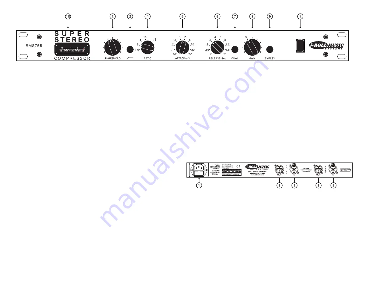
1.
Power Switch.
After confirming and connecting the correct mains
voltage, push switch up to engage power.
2.
Threshold.
Continuously variable control of threshold level, above
which gain reduction begins to occur. Exact threshold level depends
on the settings of the other controls.
3.
Sidechain Hi-Pass Filter.
Pushbutton switch removes low-frequency
information from the control signal. This can prevent unwanted
“pumping” on bass notes, such as kick drum. Filter is factory configured
for 150Hz corner frequency. Press button in to engage filter.
4.
Ratio.
4-position rotary switch selects one of four compression ratios:
1.5:1; 2:1; 4:1; or 10:1. Changing the ratio will automatically adjust
the threshold so that the total amount of gain reduction will remain
approximately the same, allowing for more meaningful comparison of
the audible effects of different ratio settings.
5.
Attack Time.
10-position rotary switch selects one of ten attack time
settings. This controls how quickly gain reduction begins to occur. A
slower attack time will allow more transients to be passed without gain
reduction; a faster attack will tend to reduce transient levels. A wide
range of tonal variation is possible as a result. Attack times are
approximate and are measured in milliseconds.
6.
Release Time.
10-position rotary switch selects one of ten release
time settings. This controls how quickly full signal level is restored
after gain reduction occurs. A fast release time will increase the
audibility of the sustain, decay, and reverberant portions of the sound.
A slower release will tend to be less noticeable on full program material.
Release times are approximate and are measured in seconds.
7.
Dual Release Time.
Pushbutton switch activates Program Dependent
Release Time mode. This mode features a dual release characteristic
which offers a slower recovery from long passages of above-threshold
signal as well as a faster recovery from short transients. The Release
Time control switch continues to function in this mode, affecting the
“short” portion of the release characteristic. However, the release
times printed on the faceplate are not accurate in Dual mode.
8.
Makeup Gain.
Continuously-variable control of output gain applied to
all signal, indepently of any gain reduction occurring. Range of the gain
control is -14dB to +20dB. Since this gain is applied after the com-
pression circuitry, it is possible to cause output clipping by excessive
clockwise rotation of the Gain control.
9.
Bypass.
Pushbutton switch bypasses all circuitry. This is a true hard-
wire bypass, so there is no active circuitry in the signal path when the
bypass switch is engaged. It is equivalent to unplugging the input and
output XLR cables from the unit and connecting them to one another.
10.
Gain Reduction Meter.
Displays instantaneous degree of gain
reduction in Decibels. Meter is not affected by applied Makeup Gain.
1.
Mains power connector and fuse holder.
Mains power is applied via
a standard IEC 3-prong power cord (included). Mains voltage is selected
internally at the factory for 117VAC or 230VAC nominal mains, and can
be reconfigured internally by a qualified service technician. Connect the
power cord only to a properly grounded outlet of correct mains voltage.
2.
Balanced XLR audio input connectors.
Stereo Audio input is on a
pair of electronically balanced XLR-F connectors with differential signal
between pins 2 and 3 (pin 1 connects to chassis ground). Unbalanced
sources should be connected between pins 2 and 1.
3.
Balanced XLR audio output connectors.
Stereo Audio output is on a
pair of electronically balanced XLR-M connectors with differential signals
between pins 2 and 3. Unbalanced loads should be connected between
pins 2 and 1, with pin 3 left unconnected. Do not ground the unused pin.
RMS755 SUPER STEREO COMPRESSOR FRONT PANEL CONTROL FEATURES
REAR PANEL CONNECTION DIAGRAM


