background image

D1

D2

D1

D2

D1

D2

D1

D2

D1

D2

D1

D2

D1

D2

D1

D2

D1

D2

D1

D2

D1

D2

D1

D2

Page 4

ZIPSCREEN EXTREME Installation Manual | SEP 2020

2020 © Copyright All Rights Reserved Rollease Acmeda

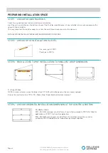
PREPARING INSTALLATION SPACE

STEP 2 - CHECK TOP OF INSTALLATION IS LEVEL

STEP 3 - PACK & LEVEL TOP OF INSTALLATION TO SMALLEST DROP DIMENSION

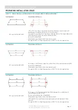
STEP 4 - CHECK HORIZONTAL INSTALLATION DIMENSION AT TOP, CENTRE & BOTTOM

SECTION 1 - INSTALLATION PREPARATION

If un-even, go to STEP 3
If level, go to STEP 4

D = Drop of Shade
NOTE: In some instances, when the drop is level, D1 & D2 will not be equal as there is uneven ground
Ensure the smallest value of D1 & D2 = Shade Drop ID specified in initial measurement

W = Width of blind
If W1, W2 & W3 are equal or within 7mm of each other, proceed to STEP 6 for Side Fix 
applications or STEP 7 for Face Fix applications
If W1, W2 & W3 are not equal or within 7mm of each other, review the scenarios 
outlined in STEP 5 and determine if and where packing is required

STEP 1 - CHECK FOR OBSTRUCTIONS

Check for any obstructions that may interfere in installation
eg If there is an architrave at the bottom of a post that the Zipscreen Extreme is to be installed into, ensure you prepare the 

space for the installation
This may mean that the installer needs to cut into the architrave to make room for the side rails

NOTE: AVOID INSTALLING ZIPSCREEN EXTREME IN WINDY CONDITIONS

Summary of Contents for Zipscreen Extreme

Page 1: ...ZIPSCREEN EXTREME INSTALLATION MANUAL...

Page 2: ...rom errors in or omissions from the information included herein Rollease Acmeda reserves the right to make changes without further notice to any products to improve reliability function or design COPY...

Page 3: ...y be required Screw For Bracket M10 Type and length indicative of mounting surface Screw Self Tapping Type AB Phillips Pan Head 6 x 5 8 Stainless Steel Screw Self Tapping Type AB Phillips Pan Head 6 x...

Page 4: ...Ensure the smallest value of D1 D2 Shade Drop ID specified in initial measurement W Width of blind If W1 W2 W3 are equal or within 7mm of each other proceed to STEP 6 for Side Fix applications or STEP...

Page 5: ...nsure W1 Blind Width Blind width is specified in initial check and measure Proceed to STEP 6 for Side Fix applications or STEP 7 for Face Fix applications W1 is greater than W2 W3 Pack space so that t...

Page 6: ...SIDE FIX APPLICATIONS ONLY STEP 7 CHECK ENSURE THE INSTALLATION IS LEVEL SQUARE If X1 or X2 is less than 7mm no packing necessary however a square space will provide greater flexibility with the rest...

Page 7: ...m 1 06 156mm 6 14 4x 12mm 0 47 34mm 1 34 34mm 1 34 95 50mm 3 76 47mm 1 85 102mm 4 02 62mm 2 44 4x 13mm 0 51 NG W FRO BOX 190 Refer to deductions for bracket positioning Ensure brackets are installed a...

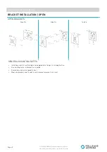
Page 8: ...S BRACKET INSTALLATION OPEN SECTION 2 INSTALLATION Face Fix Side Fix Top Fix GENERAL MOUNTING NOTES Install brackets to wall ceiling using appropriate fixings to suit application Use existing holes in...

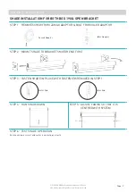
Page 9: ...T IS CENTRED WITH SYSTEM SHADE INSTALLATION FOR BOTH BOX 190 OPEN BRACKET STEP 1 REMOVE SCREW FROM ZAMAK ADAPTOR BOLT FROM IDLER ADAPTOR STEP 2 MOUNT SHADE TO BRACKETS MOTOR END FIRST STEP 3 FASTEN SH...

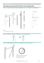
Page 10: ...ION FOR BOTH BOX 190 OPEN BRACKET SECTION 2 INSTALLATION STEP 1 MOUNT FIXING RAIL TO WALL ON BOTH SIDES FOR FACE APPLICATIONS ONLY TOP VIEW IMPORTANT FASTENERS MUST BE SUITABLE FOR FIXING TO SUBSTRATE...

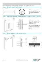
Page 11: ...CTION 2 INSTALLATION STEP 2 ALIGN U MOUNTING RAIL INTO BRACKET CUT OUT MOUNT TO FIXING RAIL STEP 3 REMOVE STOPS FROM THE FUNNEL IN THE INNER RAILS STEP 4 SWING INNER RAIL INTO THE U MOUNTING RAIL ON A...

Page 12: ...ION NOTE If there is inadequate access to the back of the blind re attach stops add only to the front of the blind on both ends NOTE The distance between the weight bar end cap and the edge of the inn...

Page 13: ...8 MOUNT SECOND FIXTURE INTO THE U MOUNTING RAIL STEP 9 FIX REMAINING SIDE GUIDE SCREWS AND SECURE STEP 10 TEST OPERATION AND APPEARANCE OF SHADE Run blind down and secure the Inner Rail at the bottom...

Page 14: ...nual SEP 2020 2020 Copyright All Rights Reserved Rollease Acmeda BOX 190 ONLY FRONT COVER SECTION 2 INSTALLATION STEP 1 FIX BOX 190 FRONT COVER IN PLACE NOTES Fixing points dependant on installation a...

Page 15: ...N BRACKET If fabric cannot be centred check scallop in fabric is large enough for installation Assembly manual If the fabric at the scallop is flush with the edge of the tube and the fabric cannot mov...

Page 16: ...torised system and no damage will be caused as a result If undesired avoid operating blind in windy conditions Not enough weight in Weight Bar Add ballast to Weight Bar Refer Assembly Manual 6 Cannot...

Reviews: