2. Start-up
2.1. Electrical connection
WARNING
Caution: Mains voltage present!
Before connecting the ROLLER slitting and
cutting machine, check whether the voltage given on the rating plate corresponds
to the mains voltage. On building sites, in a wet environment, indoors and
outdoors or under similar installation conditions, only operate the ROLLER
slitting and cutting machine with a fault current protection switch (FI switch)
which interrupts the power supply as soon as the leakage current to earth
exceeds 30 mA for 200 ms.
2.2. Choosing the diamond cutting discs
Only diamond cutting discs with a metal body in accordance with EN 13236
are approved which fit exactly onto the drive shaft (13) and have the permissible
outside diameter and permissible width. The maximum admissible speed of
the diamond cutting discs may not be lower than the speed of the ROLLER
diamond slitting and cutting machines. Up to two diamond cutting discs may
be mounted in ROLLER’S Groove 125 and up to three in ROLLER’S Groove
180 SR. Only one diamond cutting disc is mounted for cutting (see technical
data). For large slitting widths it is recommended to mount a third diamond
cutting disc approximately in the centre between the two outer ones so that the
ridges created during slitting can be broken off more easily. When using more
than one diamond cutting disc, make sure that all of them have the same outside
diameter. When using more than one diamond cutting disc, these should always
be changed in sets.
WARNING
Only use diamond cutting discs with a metal body in accordance with EN 13236.
The use of other diamond cutting discs and the use of toothed saw blades are
dangerous and therefore forbidden.
2.3. Mounting the diamond cutting discs - setting the slitting width
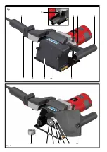
ROLLER’S Groove 125 (Fig. 1 and 2)
Pull out the mains plug. Wear suitable hand protection. The ROLLER diamond
slitting and cutting machine
is best placed on a table or on the floor. Undo the
screw (17), the screw axle (7) is firmly stuck in and may not be removed. Swing
out the protective cover (6) around the screw axle. Press the drive shaft lock
(18) and remove the hexagon head bolt (10) with a size 13 spanner. Pull the
clamping flange (11) and spacer discs (12) of the drive shaft (13). Clean the
drive shaft and all parts to be mounted. The groove width is set with the spacer
discs. Arrange the spacer discs and diamond cutting discs according to the
slitting width. The direction arrow of the diamond cutting disc must match the
direction arrow (14) on the protective cover. At least one spacer disc must be
mounted between the diamond cutting discs. All the spacer discs must be
pushed onto the drive shaft. Insert the clamping flange with the collar into the
drive shaft and make sure that the lug of the drive shaft engages into the groove
of the clamping flange. Press the drive shaft lock (18) and tighten the hexagon
head bolt (10). Check the diamond cutting discs for secure fit. Swing in the
protective cover and fasten with the screw (17). Trial run the power tool with
the newly fitted diamond cutting discs for at least one minute without load before
starting work. The position of the diamond cutting discs can be marked on the
contact plate (9) for accurate positioning of the slits.
CAUTION
Diamond cutting discs get very hot. Let them cool down before touching or
removing.
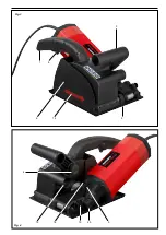
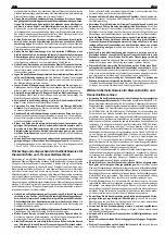
ROLLER’S Groove 180 SR (Fig. 2, 3 and 4)
Pull out the mains plug. Wear suitable hand protection. It is best to place the
ROLLER diamond slitting and cutting machine with the contact plate (9) on a
table or on the floor and hold the switch handle (1) by one hand. Pull stop bolts
(19), swing out drive unit. Press the drive shaft lock (18) and remove the hexagon
head bolt (10) with a size 13 spanner. Pull the clamping flange (11) and spacer
discs (12) of the drive shaft (13). Clean the drive shaft and all parts to be
mounted. The groove width is set with the spacer discs. Arrange the spacer
discs and diamond cutting discs according to the slitting width. The direction
arrow of the diamond cutting disc must match the direction arrow (14) on the
protective cover. At least one spacer disc must be mounted between the diamond
cutting discs. All the spacer discs must be pushed onto the drive shaft. Insert
eng eng
1.2. Article numbers
Groove 125
Groove 180 SR
ROLLER’S Groove drive unit
185000
185001
ROLLER’S Universal diamond cutting disc Ø 125 Eco
185020
ROLLER’S Universal diamond cutting disc Ø 125 LS Turbo
185021
ROLLER’S Universal diamond cutting disc Ø 125 LS H-P
185022
ROLLER’S Universal diamond cutting disc Ø 180 Eco
185025
ROLLER’S Universal diamond cutting disc Ø 180 LS Turbo
185026
ROLLER’S Universal diamond cutting disc Ø 180 LS H-P
185027
ROLLER’S Protector L, wet and dry vacuum cleaner of dust class L
185500
185500
ROLLER’S Protector M, wet and dry vacuum cleaner of dust class M
185501
185501
Slitting chisel
185024
185024
Steel case
185058
185058
1.3. Applications
Max. slit depth
38 mm
63 mm
Slit width
7 to 43 mm
7 to 62 mm
Number of diamond cutting discs
1 to 2
1 to 3
1.4. Speed
230 V/115 V
230 V/115 V
Idle
7,900 rpm/8,300 rpm
5,000 rpm/5,000 rpm
Rated load
5,000 rpm/6,500 rpm
5,000 rpm/5,000 rpm
1.5. Approved diamond cutting discs
Groove 125
Groove 180 SR
Mounting bore diameter
22.23 mm (⅞”)
22.23 mm (⅞”)
Max. outer diameter of diamond cutting disc
125 mm
180 mm
Thickness of the diamond cutting disc
2.2 mm
2.2 mm
Only use diamond cutting discs with a metal body in accordance with EN 13236.
1.6. Electrical data
230 V ~; 50 – 60 Hz; 1,850 W; 8.5 A
230 V ~; 50 – 60 Hz; 2,000 W; 8.7 A
115 V ~; 50 – 60 Hz; 1,700 W; 15 A
115 V ~; 50 – 60 Hz; 2,000 W; 17.4 A
Fuse (mains, 230 V)
10 A (B)
10 A (B)
Fuse (mains, 115 V)
20 A
25 A
radio interference suppr.
radio interference suppr.
Protection class
ll, protection insulated
ll, protection insulated
1.7. Dimensions L × W × H
515 × 320 × 155 mm (20.3” × 12.6” × 6.1”) 295 × 210 × 350 mm (11.6” × 8.3” × 1.8”)
1.8. Weight
without mains lead
5.8 kg (12.8 lb)
7.2 kg (15.9 lb)
1.9. Noise information
Workplace-related emission value
L
pA
= 90 dB (A); L
WA
= 101 dB (A); K = 3 dB
1.9.1. Vibrations
Weighted rms value of acceleration
< 2.5 m/s² K = 1.5 m/s²
The indicated weighted effective value of acceleration has been measured against standard test procedures and can be used by way of comparison with another
device. The indicated weighted effective value of acceleration can also be used as a preliminary evaluation of the exposure.
CAUTION
The indicated weighted effective value of acceleration can differ during operation from the indicated value, dependent on the manner in which the device is used. Dependent
upon the actual conditions of use (periodic duty) it may be necessary to establish safety precautions for the protection of the operator.

