28
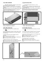
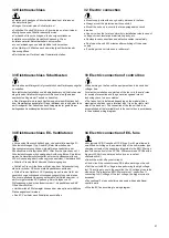
35 Platinen
•
Die Platinen können auf einer (TS 35) Hutschiene befestigt
werden.
•
Der Elektroanschluss ist gemäß dem beiliegenden Schaltplan
auszuführen.
Platine zur Ansteuerung von EC- Gebläsen (57000100)
Die Platine dient der Umwandlung eines 3 stufigen 230 V Signals in
ein 0- 10 V Signal.
•
Zur Feineinstellung der Gebläsestufen ist ein Spindeltrimmer auf
der Platine installiert.
•
Stufe 1: 1,4- 3 V
•
Stufe 2: 3- 6,8 V
•
Stufe 3: 4,4- 10 V
Universalplatine potentialfreie Kontakte/ Master- Slave
(57000101)
Die Platine kann potentialfreie Kontakte, sowie Ventilatorstufen bei
Master/ Slave Geräten, schalten.
35 Control boards
•
The circuit boards can be mounted on a (TS 35) DIN rail.
•
The electric connection has to be accomplished according to the
enclosed wiring diagram.
Circuit board to control EC fans (57000100)
The circuit board is designed to transform a 3 stepped 230 V signal
into a 0- 10 V signal.
•
For fine adjustment of fan steps a potentiometer is mounted on
the circuit board.
•
Step 1: 1,4- 3 V
•
Step 2: 3- 6,8 V
•
Step 3: 4,4- 10 V
Universal circuit board potential- free contacts/ Master- Slave
(57000101)
The circuit board switches potential- free contacts or the fan steps
at Master/ Slave units.
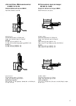
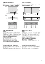
36 Vereisungsschutzthermostat
Einfriergefahr!
Bei Klimageräten mit Zweikreiswärmeaustauschern Variante 2
(Kühlen mit Kältemittel, Heizen mit Warmwasser) ist der
Vereisungsschutzthermostat in die Regelung einzubinden!
Schaltpunkte Vereisungschutzthermostat: Öffnen 3 °C ± 2,2 K,
Schließen 10 °C ± 2,2 K.
36 Anti- icing thermostat
Freezing danger!
At fan coils with a dual- circuit heat exchanger variant 2 (cooling
with refrigerant, heating by hot water) embed the anti- icing
thermostat into the control.
Switching points anti- freezing thermostat: Opens: 3 °C ± 2,2 K,
Closes 10 °C ± 2,2 K.
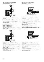
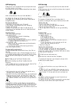
37 Elektrische Zusatzheizung
•
1 oder 2 Heizstäbe, mit 2 Sicherheitsthermostaten 80 °C
(HKN/D 200- 700)
•
1- 3 Heizstäbe, mit 2 Sicherheitsthermostaten 80 °C
(HKN/D/I/L 800-1400 )
Achtung:
Ein Betrieb der Heizungen ohne fachgerechten Anschluss der
Sicherheitsthermostate ist nicht erlaubt!
Um die zulässige Luftaustrittstemperatur nicht zu überschreiten
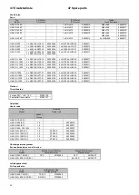
müssen die in der nachfolgenden Tabelle minimalen Gebläsestufen
eingehalten werden! Bei Betrieb ohne Gehäuse ist ein bauseitiger
Berührungsschutz am Luftaustritt zu installieren,
Verbrennungsgefahr!
Elektrischer Anschluss siehe beigelegter Schaltplan.
Achtung:
Beim Einsatz mit zusätzlichen Anbauten, d.h. zusätzlichen
luftseitigen Druckverlusten, muss eine komplette Neubewertung des
Überhitzungsrisikos der Anlage vorgenommen werden.
37 Electric booster heaters
•
1 or 2 electric booster heaters, with 2 safety thermostats 80 °C
(HKN/D 200- 700)
•
1- 3 booster heaters, with 2 safety thermostats 80 °C
(HKN/D/I/L 800- 1400)
Attention:
Operation of the heaters without professional connection of the
safety thermostats is not permitted.
Not to exceed the permissible air outlet temperature the minimum
speed settings in the following table have to be kept! If the fan coil
is operated without housing a protection against accidental contact
at the air outlet has to be installed on site.
Caution! Very hot, can cause burns!
For electric connection see enclosed wiring diagram.
Attention:
The operation with additions that, means additional air pressure
loss, has to lead to a complete reassessment of risk of excessive
heat.
Grundgerät
Anzahl
Heizleistung ~ 230V, 50 Hz
Min. Gebläsestufe
Basic unit
Number
Heating capacity 230V, 50 Hz
Min. speed setting
Pro Heizstab
Gesamt
1 Heizstab
2 Heizstäbe
3 Heizstäbe
Per heater
Total
1 heater
2 heaters
3 heaters
HKN/D
kW
kW
200
1/ 2
0,85
0,85/ 1,70
2
4
-
400
1/ 2
1,40
1,40/ 2,80
2
4
-
600
1/ 2
2,00
2,00/ 4,00
3
5
-
700
1/ 2
2,00
2,00/ 4,00
2
4
-
HKN/D/I/L
800
1/ 2/ 3
1,50
1,50/ 3,00/ 4,50
2
2
3
1000
1/ 2/ 3
2,00
2,00/ 4,00/ 6,00
2
2
3
1200
1/ 2/ 3
2,50
2,50/ 5,00/ 7,50
2
2
3
1400
1/ 2/ 3
2,20
2,50/ 5,00/ 7,50
2
2
3

