background image

20 

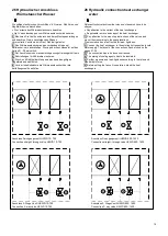
27  Kondensatablauf 


Das Gerät ist waagrecht zu installieren um einen korrekten 

Kondensatablauf im Inneren sicherzustellen.


1.

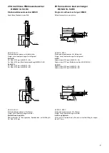
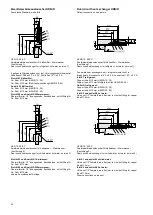
 Den Kondensatablauf mit Gefälle ausführen. Anschlussmaße 

siehe folgende Seiten. Ist dies nicht möglich, eine Kondensatpumpe 
einsetzen. 

2.

  Beachten Sie bei dem Anschluss an die Kanalisation die örtlichen 

Vorschriften für die Einleitung von Kondensaten. Sehen Sie ein 
Siphon und eine Rückschlagsicherung vor.  

3.

 Den Kondensatablauf auf Dichtheit und Funktion testen. 

27 Condensate drain 

 The unit has to be leveled out to ensure a correct 

condensate drain. 

1.

 Install the condensate drainage with a downward gradient. See 

the following pages for the connection layout. 

If this isn’t possible 

use a condensate pump. 

2.

 Install a siphon as well as a nonreturn finger and pay attention to 

the local rules and standards for discharging condensates. 

3.

 Check condensate drainage for function and tightness. 


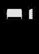
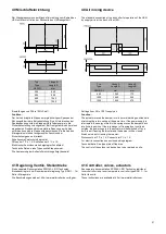
Beispiel: Kondensatablauf am Deckengerät. 

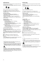
Beispiel: Kondensatablauf am Standgerät. 

Example: Condensate drain at ceiling unit. 

Exampke: Condensate drain at ceiling unit. 


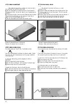
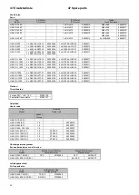
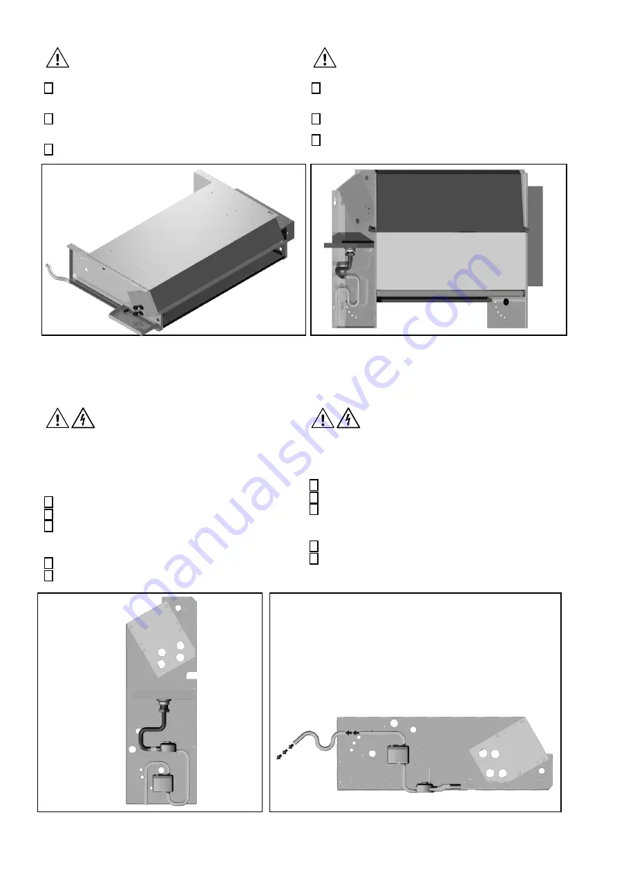
28  Kondensatpumpe 

Die Kondensatpumpe ist am Fuß der Tropfschale montiert. 


Auch bei ausgeschaltetem Gerät kann Kondensat anfallen. Stellen 
Sie sicher, dass die Kondensatpumpe auch bei ausgeschaltetem 
Gerät funktioniert. 


Im Falle einer Nachrüstung sind die folgenden Schritte zu 
absolvieren: 

1.

 Die Pumpe an das Seitenteil schrauben. 

2.

 Den Schwimmerschalter am tiefst- möglichen Punkt anbringen. 

3.

 Schwimmerschalter mit Pumpe verbinden. 


Folgende Schritte müssen immer durchgeführt werden. 

4.

 Der elektrische Anschluss der Pumpe ist bauseits durchzuführen. 

5.

 Die Montageanleitung der Kondensatpumpe beachten. 

28 Condensate pump 

The condensate pump is mounted near the drain pan at the stand. 


Even if the unit is switched off condensate may occur. Ensure that 
the condensate pump is working when the unit is switched off. 


In case of retro- fit of the condensate pump, do the following steps: 

1.

 Screw the pump to the stand. 

2.

 Mount the floating switch at the lowest possible point. 

3.

 Connect the floating switch to the pump. 


The following steps have to be done always. 

4.

 The electric connection has to be sold on site. 

5.

 Pay attention to the mounting instructions of the condensate 

pump. 


Summary of Contents for HKN/D 10 - 50 EC

Page 1: ...Montageanleitung Mounting instructions Gebläsekonvektoren Fan coil units HKN D 10 50 EC HKN D 200 700 EC HKN D I L 800 1400 EC ...

Page 2: ...o EC Machinery directive 2006 42 EC has been declared Die verwendeten Einzelkomponenten sind konform mit den jeweiligen auf sie zutreffenden folgenden weiteren EG Richtlinien 2006 95 EG Niederspannung 2004 108 EG EMV und 97 23 EG Druckgeräte The incorporated component parts are in conformity with the following additional EC Directives 2006 95 EC Low Voltage 2004 108 EC EMC and 97 23 EC Pressure Eq...

Page 3: ...als HKN 8 12 Basic unit HKN 10 50 EC 9 13 Basic unit HKND 10 50 EC 9 14 Basic unit HKN 200 700 EC 10 15 Basic unit HKND 200 700 EC 11 16 Basic unit HKN 800 1400 EC 12 17 Basic unit HKND 800 1400 EC 13 18 Installation of standing unit 14 19 Installation of ceiling unit 15 20 Drilling draft HKN D 10 50 EC 16 21 Drilling draft HKN D 200 700 EC 16 22 Drilling draft HKN I L 800 1400 EC 16 23 Drilling d...

Page 4: ... Kinder weiträumig abgesichert werden Vor allen Arbeiten an der Anlage Strom abschalten und gegen unbefugtes Einschalten sichern Vorsicht an Wänden und Decken in denen Strom Gas und Wasserleitungen verlegt sein könnten 5 Eigenmächtige Umbauten Umbauten und Veränderungen an der Anlage sind nicht gestattet 6 Sicherheit Nach dem Einbau in die Kälteanlage müssen die vom Gerät ausgehenden Sicherheitsri...

Page 5: ...ustauscher Kühlen mit Kältemittel Heizen mit Warmwasser Variante 3 ab HKN D 200 Einkreiswärmeaustauscher Kühlen mit Kaltwasser Heizen mit Elektroheizung Variante 4 ab HKN D 200 Einkreiswärmeaustauscher Kühlen mit Kältemittel Heizen mit Elektroheizung Variante 5 Einkreiswärmeaustauscher Kühlen mit Kaltwasser oder Heizen mit Warmwasser Change over Betrieb möglich Variante 7 Einkreiswärmeaustauscher ...

Page 6: ...den Gebläsekonvektor Der Gebläsekonvektor darf nicht im teilweise demontierten Zustand betrieben werden Alle nicht bestimmungsgemäßen Verwendungen sind verboten 7 Intended application Application range Operation with circulating air outdoor air or mixed air Functions Ventilation heating cooling dehumidifying and filtering of room air The fan coil unit may only be operated with technically unobject...

Page 7: ...ry Purify the unit and store in original packiging 9 Transport Zum Transport die Originalverpackung verwenden Nur an den vorgesehenen Transportvorrichtungen mit geeignetem Hebezeug transportieren Gewichtangabe siehe Kapitel 12 17 Anlage vorsichtig transportieren Schläge und Stöße vermeiden 9 Shipping Use the original packing for transport The cooler should only be moved with intended lifting devic...

Page 8: ...ten Stahlblech sendzimirverzinkt 9 Anschlussdose Kasten Polycarbonat Membranen aus TPE Deckel Polystyrol Schutzart IP 54 Basic unit HKN 1 Basic unit Material Hot dip galvanized sheet steel 2 Heat exchanger Copper tubes Cu DHP Aluminum fins EN AW 8006 Copper fins Cu DHP prelacquered fins 3 Drain pan Hot dip galvanized sheet steel powder coated insulated against condensate formation 4 Cross flow fan...

Page 9: ...s in mm EC cross fan blower 220 240 V 50 60 Hz Weight Tube volume Sound pressure Anzahl Leistung Stromaufn Drehzahl 2 Leiter 4 Leiter WT1 WT2 Number Input cap Curr Cons r p m 2 lines 4 lines HX1 HX2 HKN D A B C W A min 1 kg kg dm dB A 10 580 445 430 1 38 0 32 1500 15 16 0 7 0 2 22 45 20 780 645 630 1 38 0 32 1500 18 19 1 1 0 4 23 46 30 980 845 830 1 38 0 32 1500 19 21 1 4 0 5 24 47 40 1180 1045 10...

Page 10: ...1 2 6 2 1 1 4 23 50 Schalldruckpegel in 1 m Abstand Grundgerät mit Filter und Gehäuse Sound pressure levels at a distance of 1 m Basic unit with air filter and housing AC Radialgebläse 230 V 50 60 Hz EC Radialgebläse 230 V 50 60 Hz AC Radial blower 230 V 50 60 Hz EC Radial blower 230 V 50 60 Hz Anzahl Leistung Stromaufn Drehzahl Anzahl Leistung Stromaufn Drehzahl Number Input cap Curr Cons r p m N...

Page 11: ...Schalldruckpegel in 1 m Abstand Grundgerät mit Filter und Gehäuse Sound pressure levels at a distance of 1 m Basic unit with air filter and housing Grundgerät AC Radialgebläse 230 V 50 60 Hz EC Radialgebläse 230 V 50 60 Hz Basic unit AC Radial blower 230 V 50 60 Hz EC Radial blower 230 V 50 60 Hz Anzahl Leistung Stromaufn Drehzahl Anzahl Leistung Stromaufn Drehzahl Number Input cap Curr Cons r p m...

Page 12: ...1200 2170 1940 1800 1860 1983 75 5 5 6 2 4 1 2 1 24 49 1400 2670 2440 2300 2360 2483 90 6 8 7 7 5 1 2 6 25 50 Schalldruckpegel in 1 m Abstand Grundgerät mit Filter und Gehäuse Sound pressure levels at a distance of 1 m Basic unit with air filter and housing Grundgerät AC I Gebläse 230 V 50 60 Hz AC L Gebläse 230 V 50 60 Hz EC Gebläse 230 V 50 60 Hz Basic unit AC I Blower 230 V 50 60 Hz AC L Blower...

Page 13: ...3 9 2 9 1 5 20 45 1000 1870 1640 1500 1560 753 73 4 7 5 3 3 5 1 8 23 48 1200 2170 1940 1800 1860 903 85 5 5 6 2 4 1 2 1 24 49 1400 2670 2440 2300 2360 1153 103 6 8 7 7 5 1 2 6 25 50 Grundgerät AC I Gebläse 230 V 50 60 Hz AC L Gebläse 230 V 50 60 Hz EC Gebläse 230 V 50 60 Hz Basic unit AC I Blower 230 V 50 60 Hz AC L Blower 230 V 50 60 Hz EC Blower 230 V 50 60 Hz Anzahl Leistung Stromaufn Drehzahl ...

Page 14: ... Installation z B hinter einer Brüstung des Klimagerätes ist folgendes zu beachten Revisionsöffnungen für Filterwechsel und zur Reinigung der Kondenswasser führenden Teile vorsehen 18 Installation of standing unit The unit may only be installed by authorized and skilled personnel Be careful at walls and ceilings that could contain electric wires gas and water piping For fixation we recommend screw...

Page 15: ...ndes zu beachten Revisionsöffnungen für Filterwechsel und zur Reinigung der Kondenswasser führenden Teile vorsehen Zeichnungen und Hinweise für Übergangsstücke z B Segeltuchstutzen s Kapitel Anschlussmaße 19 Installation of ceiling unit The unit may only be installed by authorized and skilled personnel Be careful at walls and ceilings that could contain electric wires gas and water piping For fixa...

Page 16: ... mm Basic unit Dimensions in mm HKN D A B 10 580 445 20 780 645 30 980 845 40 1180 1045 50 1380 1245 21 Bohrskizze HKN D 200 700 EC 21 Drilling draft HKN D 200 700 EC Grundgerät Abmessungen in mm Basic unit Dimensions in mm HKN D A B 200 870 660 400 1 170 960 600 1 470 1 260 700 1 470 1 260 ...

Page 17: ...nit Dimensions in mm HKNDL I A B 800 1570 1340 1000 1870 1640 1200 2170 1940 1400 2670 2440 23 Bohrskizze HKND I L 800 1400 EC 23 Drilling draft HKND I L 800 1400 EC Grundgerät Abmessungen in mm Basic unit Dimensions in mm HKNDL I A B C 800 1570 1383 603 1000 1870 1683 753 1200 2170 1983 903 1400 2670 2483 1153 ...

Page 18: ... 25 Hydraulischer Anschluss Wärmetauscher Kältemittel Die gültigen technischen Vorschriften d h Normen Richtlinien und Regelwerke sind einzuhalten Die Variante des Wärmeaustauschers beachten 1 Verschlusskappen vom Wärmeaustauscher abnehmen 2 Montieren Sie Ventile entsprechend deren Montageanleitung 3 Den Wärmeaustauscher an das vorhandene Kältemittelnetzwerk anschließen Die Lage der Anschlüsse ist...

Page 19: ...r Relevant technical advices like rules and standards have to be obeyed Pay attention to the variant of the heat exchangers If applicable remove end caps of the heat exchanger 1 Pay attention to the mounting instructions of the valves and mount them according to these explanations Premounted valves aren t tested for leak tightness 2 Connect the heat exchanger to the existing hot respectively cold ...

Page 20: ...at ceiling unit Exampke Condensate drain at ceiling unit 28 Kondensatpumpe Die Kondensatpumpe ist am Fuß der Tropfschale montiert Auch bei ausgeschaltetem Gerät kann Kondensat anfallen Stellen Sie sicher dass die Kondensatpumpe auch bei ausgeschaltetem Gerät funktioniert Im Falle einer Nachrüstung sind die folgenden Schritte zu absolvieren 1 Die Pumpe an das Seitenteil schrauben 2 Den Schwimmersch...

Page 21: ... HKN D 40 50 HKND 10 50 EC Einkreiswärmeaustauscher für Kältemittel Single circuit heat exchanger for refrigerant Inlet E Copper tube Ø 10 mm HKN D 10 30 Copper tube Ø 10 mm Multiple injection HKN D 40 50 Outlet A Copper tube Ø 10 mm HKN D 10 30 Copper tube Ø 15 mm HKN D 40 50 HKN 10 50 EC Einkreiswärmeaustauscher für Wasser Single circuit heat exchanger for water Eintritt E und Austritt A Überwur...

Page 22: ...10 C 2 2 K Inlet E1 refrigerant Copper tube Ø 10 mm HKN D 10 30 Copper tube Ø 12 mm Multiple injection HKN D 40 50 Outlet A1 refrigerant Copper tube Ø 10 mm HKN D 10 30 Copper tube Ø 15 mm HKN D 40 50 Inlet E2 and outlet A2 hot water Union nut 1 2 female thread flat joint incl solder fitting for copper tube Ø 15 mm HKN 10 50 EC Zweikreiswärmeaustauscher für Kaltwasser Warmwasser Ausführung 2 Dual ...

Page 23: ...D 400 700 Austritt A Cu Rohr Ø 10 mm HKN D 200 Cu Rohr Ø 15 mm HKN D 400 Cu Rohr Ø 22 mm HKN D 600 700 Inlet E Copper tube Ø 10 mm HKN D 200 Copper tube Ø 12 mm Multiple inkjection HKN D 400 700 Outlet A Copper tube Ø 10 mm HKN D 200 Copper tube Ø 15 mm HKN D 400 Copper tube Ø 22 mm HKN D 600 700 Eintritt E und Austritt A Überwurfmutter 1 2 Innengewinde flachdichtend mit Lötfitting für Cu Rohr Ø 1...

Page 24: ...sconnects at 3 C 2 2 K connects at 10 C 2 2 K Inlet E1 refrigerant Copper tube Ø 10 mm HKN D 200 Copper tube Ø 12 mm Multiple injection HKN D 400 700 Outlet A1 refrigerant Copper tube Ø 10 mm HKN D 200 Ø 15 mm HKN D 400 Copper tube Ø 22 mm HKN D 600 700 Inlet E2 and outlet A2 hot water Union nut 1 2 female thread flat joint incl solder fitting for copper tube Ø 15 mm Eintritt E1 und Austritt A1 Ka...

Page 25: ...hr Ø 22 mm HKN D I L 800 Cu Rohr Ø 28 mm HKN D I L 1000 1400 Inlet E Copper tube Ø 12 mm Multiple injection HKN D I L 800 1200 Copper tube Ø 15 mm Multiple injection HKN D I L 1400 Outlet A With schrader valve Copper tube Ø 22 mm HKN D I L 800 Copper tube Ø 28 mm HKN D I L 1000 1400 Eintritt E und Austritt A Sechskantmuffe mit Entlüftungsventil R 1 8 am Eintritt HKNI HKNL bzw am Austritt HKNDI HKN...

Page 26: ... refrigerant Copper tube Ø 12 mm Multiple injection Outlet A1 refrigerant Copper tube Ø 22 mm with schrader valve Inlet E2 and outlet A2 hot water Hexagon sleeve R 1 2 with vent valve R 1 8 at the inlet HKNI HKNL resp at the outlet HKNDI HKNDL Eintritt E1 und Austritt A1 Kaltwasser Sechskantmuffe R 3 4 mit Entlüftungsventil R 1 8 am Eintritt HKNI HKNL bzw am Austritt HKNDI HKNDL Eintritt E2 und Au...

Page 27: ... box resp a terminal box It is on the right or left side of the basic unit The connection of the fan coil has to be accomplished at the terminal block in the control box in accordance to the enclosed wiring diagram 34 Elektroanschluss EC Ventilatoren Verwenden Sie ausschließlich puls und oder allstromseitige FI Schutzeinrichtungen Typ A oder B Beim Einschalten der Spannungsversorgung können impuls...

Page 28: ... Sicherheitsthermostaten 80 C HKN D 200 700 1 3 Heizstäbe mit 2 Sicherheitsthermostaten 80 C HKN D I L 800 1400 Achtung Ein Betrieb der Heizungen ohne fachgerechten Anschluss der Sicherheitsthermostate ist nicht erlaubt Um die zulässige Luftaustrittstemperatur nicht zu überschreiten müssen die in der nachfolgenden Tabelle minimalen Gebläsestufen eingehalten werden Bei Betrieb ohne Gehäuse ist ein ...

Page 29: ...rsion Material Housing made of galvanized steel sheet powder coated white similar RAL 9010 optional RAL 7035 lightgrey Inlet and Outlet made of aluminum alloy Surface black anodized optional silver anodized Side panels detachable as an option Abmessungen Gewichte HKN D 10 50 Dimensions Weights HKN D 10 50 Gehäuse Länge A Gewicht Housing Length A Weight HKN D mm kg 10 750 7 20 950 9 30 1150 10 40 1...

Page 30: ... Seitenteil einstecken und im Lufteintritt mit einer Flügelschraube fixieren 39 Mounting of housing 1 Hinge the housing at the bottom of the unit and impose on itsself The housing of the ceiling unit HKND 800 1400 has to be hinged on the top and pushed at the bottom 2 Fix the housing by means of sheet metal screw threads 4 2x16 in the air inlet and outlet 3 Put the air outlet grille in the outlet ...

Page 31: ...k of the HKN Settings from 30 to 100 supply air Function The actuator moves the damper into its normal working position while stretching the return spring at the same time If the power supply is interrupted the energy stored in the spring moves the damper back into its safe position If there is danger of freezing due to cold air outside the power supply to the actuator will be switched off by a bu...

Page 32: ... und wischen Sie es gründlich aus Bei HKN D 10 50 EC ist der Schaltkasten direkt unterhalb des Tropfbleches angebracht Entnehmen Sie das Tropfblech vorsichtig Bei HKN D 200 1400 EC sind die Ventilatoren am Tropfblech montiert Lösen Sie zuerst den Stecker der Ventilatoren bevor sie die Tropfschale komplett entnehmen 42 Cleaning Unit may only be serviced and repaired by authorized and skilled person...

Page 33: ...ay only be serviced and repaired by authorized and skilled personnel At least every 6 months the following services have to be done Check the Mounting of the unit Unit for damages and completness Fan for damanges Screws and tighten if necessary Clean air inlet and outlet grilles Bleed heat exchangers for water brines Connection of the protective conductor Connection of the supply lines Insulation ...

Page 34: ...46 LV19 15 56000200 5 x D3G146 LU03 34 56000311 HKN D I 800 2 x D4E146 LX77 21 56000196 2 x D3G146 LU03 34 56000311 HKN D I 1000 3 x D4E146 LX77 21 56000196 3 x D3G146 LU03 34 56000311 HKN D I 1200 4 x D4E146 LX77 21 56000196 4 x D3G146 LU03 34 56000311 HKN D I 1400 5 x D4E146 LX77 21 56000196 5 x D3G146 LU03 34 56000311 Platinen Circuit boards 3 step 230 V to 0 10 V 57000100 3 potential free cont...

Page 35: ...C 0100051 22100082 22100087 0150032 HKN D 40 EC 0100052 22100083 22100088 0150033 HKN D 50 EC 0100053 22100084 22100089 0150034 HKN D 200 0100025 22100068 22100071 0150009 HKN D 400 0100026 22100069 22100072 0150010 HKN D 600 0100027 22100070 22100073 0150011 HKN D 700 0100027 22100070 22100073 0150011 HKN D 800 0100035 22100056 22100059 0150012 HKN D 1000 0100036 22100057 22100060 0150013 HKN D 1...

Page 36: ...ram Gerät tropft Unit drips Tropfschale übergelaufen Spill of drain pan Überprüfen auf Beschädigung und Verstopfung Check for damage and choking Ablauf verstropft Drain choked Ablauf reinigen Clean drain Umgebungstemperatur und Luftfeuchte zu hoch Ambient temperature und humidity too high Einsatzgrenzen auf Seite 7 überprüfen Check diagram on page 7 Wärmeaustauscher vereist Icing of heat exchanger...

Reviews: