eng eng
The oxidising effect of the disinfectant can be rendered ineffective by adding
reducers. The pH value must also be observed and corrected if necessary.
An application concentration for the dosing solution for hydrogen peroxide H
2
An application concentration for the dosing solution for hydrogen peroxide H
An application concentration for the dosing solution for hydrogen peroxide H O
2
of 150 mg H
2
O
2
/ l and an exposure time of 24 hours are recommended.
22
Information leafl et "Flushing, disinfection and commissioning of drinking
water installations" (August 2014) of the German Central Association for
Sanitary, Heating and Air Conditioning (ZVSHK)
The following must be observed for Germany
Germany: "At the end of disinfection, the
Germany
Germany
entire system must be fl ushed at all tapping points until the concentration of
the disinfectant at all tapping points measured at the transition point (usually
the water meter) is reached or dropped below again.
To be observed for disposal: "If the water used for disinfection of an installation
is to be drained into a drain pipe or sewer, the responsible department must be
informed and the water may only be drained when the responsible department
has granted its permission." "Because of the rapid decomposition, the disposal
of hydrogen peroxide by draining into the sewer system is unproblematical."
A maximum line length of 100 m is specifi ed for fl ushing sections in the Euro-
pean standard EN 806-4:2010 and in the information leafl et "Flushing, Disin-
fection and Commissioning of Drinking Water Installations" (August 2014) of
the German Central Association for Sanitary, Heating and Air Conditioning
(ZVSHK). For this length a volume of approx. 20 l is required for a ½" galvanised
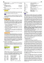
steel pipe and a volume of approx. 100 l disinfectant for a 1 ¼" pipe (see Fig.
6: Volume in l/m of different pipes).
6: Volume in l/m of different pipes
6: Volume in l/m of different pipes
Depending on the volume of the individual pipe sections, several pipe sections
can be disinfected with one bottle of ROLLER’S Plus TW-D Color dosing
solution (see Accessories 1.2. Article Numbers). However, it is recommended
not to use an opened bottle for longer than one day because the dosing solu-
tion loses in concentration. Hydrogen peroxide decomposes in time and loses
its effect depending on the environment in which it is stored. Therefore the
concentration of the dosing solution should be checked for effectiveness before
every disinfection. To do this, fi ll a clean, sealable container with 100 ml of water
and draw 1 ml of dosing solution from the bottle using the pipette provided with
every carton of ROLLER’S Plus TW-D Color and add it to the container (ratio
1:100). Seal the container and shake well. The concentration of the container
contents is measured with the test strip (Art. No. 091072) according to the
instructions printed on the test strip package. This should be ≥ 150 mg/l H
2
instructions printed on the test strip package. This should be ≥ 150 mg/l H
instructions printed on the test strip package. This should be ≥ 150 mg/l H O
2
.
Open the bottle (21), remove the locking ring from the bottle cap and pour the
delivered dye (20 ml bottle) into the bottle (21) immediately before the disin-
fection process. Close the bottle and shake it so that the dye mixes evenly with
the hydrogen peroxide.
CAUTION
CAUTION
The dye is not harmful to the health but very intensive and is very diffi cult to
remove from the skin or clothing. Therefore pour the dye into the bottle carefully.
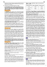
Fit bottle to the disinfection unit ROLLER’S Inject TW as shown in Fig. 7 (21).
The nozzles installed in ROLLER’S Inject TW and ROLLER’S Inject H for
automatic dosing of dosing solution, cleaner and corrosion protection are
different sizes and adapted to the properties of the ROLLER ingredients to be
injected. Therefore make absolutely sure that ROLLER’S Inject TW is connected
for disinfection of drinking water pipes.
Select program Ingredients \ disinfection
DW.
During the fi lling process, all tapping points on the drinking water instal-
lation must be opened one after another, starting with the furthest away, until
the dyed disinfection solution emerges at the respective tapping point. If the
tapping point is in a dark environment it is helpful to hold a white background
(e.g. a sheet of paper) behind the outlet in order to be able to see the disinfec-
tion solution better.
The supply to the disinfection unit before ROLLER’S Multi-Control and the drain
to the drinking water installation must be shut off at the end of the disinfection
process. Then the bottle (21) must be removed slowly so that excess pressure
Then the bottle (21) must be removed slowly so that
Then the bottle (21) must be removed slowly so that
can escape.
After 24 hours exposure (recommendation of the German Central Association
for Sanitary, Heating and Air Conditioning (ZVSHK) and recommendation of
the German Association of the Gas and Water Industry (DVGW), the disinfec-
tion solution must be fl ushed out of the drinking water installation with ROLLER’S
Multi-Control. To do this, all tapping points must be opened again one after
another, starting with the nearest, until there is no longer any trace of the dyed
disinfection solution.
Additionally, peroxide test strips can be used if necessary to check the concen-
tration (accessories, see 1.2. Article numbers).
NOTICE
NOTICE
Hoses used for disinfection/cleaning should no longer be used for pressure
testing with water and for fl ushing drinking water pipes.
3.3. Testing drinking water installations with compressed air program (ROLLER’S
Multi-Control SL/SLW)
WARNING
WARNING
For Germany the information leafl et "Leak Tests of Drinking Water Installations
with Compressed Air, Inert Gas or Water" (January 2011) of the German Central
Association for Sanitary, Heating and Air Conditioning (ZVSHK) defi nes the
following for the national regulations under "3.1 General":
"Due to the compressibility of gases, the rules for the prevention of accidents
"Working on Gas Systems" and the "Technical Rules for Gas Installations
DVGW-TRGI" must be observed for physical and safety reasons when conducting
pressure tests with air Therefore, the test pressures have been defi ned as
maximum 0.3 MPa/3 bar/43.5 psi, the same as for load and leak tests for gas
pipes, in agreement with the responsible industrial liability insurance associa-
tion and based on these rules. The national regulations are thereby fulfi lled.“
The respective national safety provisions, rules and regulations valid for
the application site must be considered and observed.
Before conducting a test with compressed air, it must be assessed whether the
installation to be tested will withstand the preset / selected test pressure "p refer".
The ambient temperature, the temperature of the test medium and the atmos-
pheric air pressure can infl uence the result of the test because they affect the
measured pressures. Changes in these parameters must be considered, if
necessary, in the evaluation of the test results.
Section 6. of EN 806-4:2010 defi nes among other things that: "Installations inside
buildings must be subjected to pressure testing. This can be done either with
water or, if national regulations allow, oil-free, clean air with low pressure or inert
gases may be used. The possible risk from high gas or air pressure in the system
must be considered." However, apart from this note, the standard EN 806-4:2010
contains no test criteria whatsoever for testing with compressed air.
The tests described below and the defaults stored in the ROLLER’S Multi-Con-
The tests described below and
The tests described below and
trol correspond to the information leafl et "Leak tests of drinking water installa-
tions with compressed air, inert gas or water" (January 2011) of the German
Central Association for Sanitary, Heating and Air Conditioning (ZVSHK). Future
changes to this information leafl et or the respective valid provisions, rules and
regulations for the application site must be considered and changed test criteria
(test sequences, pressures and times) must be corrected in the defaults.
The programs can be aborted at any time with the Esc button (10). Then all
the valves open and the pressure in the installation is released. The tests are
saved but "Cancel" is shown in the fi le.
The pressure test must be repeated if necessary or the installation must be
checked and improved.
NOTICE
NOTICE
The controller ends the control process to set the selected test pressure for
tests with compressed air ≤ 200 mbar at a tolerance of ±3 mbar and for tests
≤ 3 bar (if necessary ≤ 4 bar) at a tolerance of ±0.1 bar. This means that the
control is ended, e.g. when setting p refer = 150 mbar at a value p actual
between 147 and 153 mbar or when setting p refer = 3 bar between 2.9 and
3.1 bar. This tolerance is safe because, in the pressure test with compressed
air, the relative pressure change of pressure p refer is decisive. If ENTER is
pressed, the value p actual is taken over as p refer. So the test can also be
begun at a p refer of 153 mbar for example.
3.3.1. Leak test with compressed air (ZVSHK
3.3.1. Leak test with compressed air (ZVSHK)
3.3.1. Leak test with compressed air (ZVSHK
3.3.1. Leak test with compressed air (ZVSHK
3.3.1. Leak test with compressed air (ZVSHK
3.3.1. Leak test with compressed air (ZVSHK
Test pressure 150 hPa (150 mbar)
Program sequence ↑ ↓ (8):
Program sequence ↑ ↓ (8
Program sequence ↑ ↓ (8
1. Test \ Enter
2. Test with compressed air \ Enter
3. Leak test \ Enter
4. Check reference test pressure default (p refer) and change if necessary (11) \ ↓
5. Check stabilisation default (t stabi) and change if necessary (11) \ ↓
6. Check test time default (t test) and change if necessary (11) \ ↓
7. Actual test pressure (p actual) is adjusted to reference test pressure (p refer)
\ Enter
8. Stabilisation/wait time (t stabi) running, actual test pressure (p actual) is
changed to reference test pressure (p refer) on expiring. The stabilisation/
wait time can be ended prematurely with Enter, the test time (t test) then
begins immediately (\ Esc = cancel).
9. Display screen: Reference test pressure (p refer), actual test pressure
(p actual), differential test pressure (p diff), test time (t test) \ Enter
(p actual), differential test pr
(p actual), differential test pr
10. Esc >> Start menu \ Memory Manager, data transfer >> 3.8
3.3.2. Load test with compressed air ≤ DN 50 (ZVSHK)
3.3.2. Load test with compressed air ≤ DN 50 (ZVSHK)
Test pressure 0.3 MPa (3 bar)
Program sequence ↑ ↓ (8):
1. Test \ Enter
2. Test with compressed air \ Enter
3. Load test ≤ DN 50 \ Enter
See leak test 4. to 10. for further procedure
3.3.3. Load test with compressed air > DN 50 (ZVSHK)
3.3.3. Load test with compressed air > DN 50 (ZVSHK)
Test pressure 0.1 MPa (1 bar)
Program sequence ↑ ↓ (8):
1. Test \ Enter
2. Test with compressed air \ Enter
3. Load test > DN 50 \ Enter
See leak test 4. to 10. for further procedure
3.4. Testing drinking water installations with water programs (ROLLER’S
Multi-Control SLW)
Section 6.1 of EN 806-4:2010 offers 3 test methods A, B, C for hydrostatic
pressure testing depending on the material and size of the installed pipes. The
test methods differ in different test sequences, pressures and times.
For Germany
Germany, the information
Germany
Germany
leafl et "Leak Tests of Drinking Water Installations
with Compressed Air, Inert Gas or Water" (January 2011) of the German Central
Association for Sanitary, Heating and Air Conditioning (ZVSHK), the following is
27

