eng eng
1. Technical data
Use for the intended purpose
WARNING
WARNING
Only use the ROLLER’S Solar-Control for the intended purpose of fi lling, fl ushing
and venting solar systems, geothermal systems and fl oor/wall heater systems and
for fi lling tanks. Permissible media: heat transfer liquids, antifreeze, water, aqueous
solutions, emulsions.
All other uses are not for the intended purpose and are prohibited.
1.1. Scope of Supply
Electrical fi lling and fl ushing unit, 2 fl exible fabric hoses, instruction manual
1.2. Article numbers
ROLLER’S Solar-Control K 60
115302
ROLLER’S Solar-Control I 80
115301
PVC fabric hose ½" T60
115314
EPDM fabric hose ½" T100
115315
EPDM fabric hose ½" T165
115319
30 l plastic tank
115375
Pressure relief valve
115217
Fine fi lter with fi lter cartridge 90 μm
115323
Fine fi lter cartridge 90 μm
043054
Fine fi lter with fi ne fi lter bag 70 μm
115220
Fine fi lter bag 70 μm (10 bags)
115221
Adapter for canister lid
115379
Shut-off valve ¾"
115324
Changeover valve
115325
Changeover valve fl ow direction
115326
Machine cleaner
140119
1.3. Applications
Solar-Control I 80
Solar-Control K 60
Plastic tank volume
30 l
30 l
Transport height
≤ 63 m
≤ 54 m
Volume fl ow
≤ 1.6 m
3
/h
≤ 3 m
33
3
/h
33
Transport capacity at
40 m pumping head
18 l/min
16 l/min
Transport volume
≤ 27 l/min
≤ 36 l/min
Transport pressure
≤ 0.65 MPa/6.5 bar
≤ 0.55 MPa/5.5 bar
94 psi
80 psi
Temperature of the transpor-
ted media (constant load)
≤ 80°C
≤ 60°C
pH value of the
transported media
6.5 – 9.5
6.5 – 9.5
1.4. Electrical data
230 V~; 50 Hz;
230 V~; 50 Hz;
1000 W
860 W
110 V~; 50 Hz;
860 W
Protection class
I
I
Type of protection
IP 55
IP 44
Operating mode
S3 50% (AB
Operating mode
S3 50% (
Operating mode
S3 50% ( 5/10 min) Continuous
AB
AB
operation
1.5. Dimensions
L × W × H
550 × 480 × 970 mm 550 × 480 × 970 mm
(21.7" × 18.9" × 38.3") (21.7" × 18.9" × 38.3")
1.6. Weights
with PVC fabric hoses
20.4 kg (45 lb)
19.8 kg (43.7 lb)
with EPDM fabric hoses
20.0 kg (44.2 lb)
19,4 kg (42.9 lb)
1.7. Noise information
Workplace-related
emissions value
L
pA
= 73 dB (A)
L
pA
= 70 dB (A)
K = 3 dB (A)
K = 3 dB (A)
1.8. Suction and pressure hoses
PVC-
EPDM-
EPDM-
fabric fabric fabric
hose T60 hose T100 hose T165
Hose length
3 m
3 m
3 m
Hose
size
½" ½" ½"
Hose connector, both sides
¾"
¾"
¾"
Temperature resistance
≤ 60°C
≤ 100°C
≤ 165°C
1.9. Fine fi lter with fi ne fi lter bag 90 µm (accessory Art. No. 115323)
Rated width
DN 70
Rated volume fl ow at pressure loss
5m3/h at 20 kPa/0,2 bar/2,9 psi
Rated pressure
300 kPa/3 bar/43,5 psi
Operating temperature
≤ 45°C
Operating pressure
≤ 800 kPa/8 bar/116 psi
2. Start-up
NOTICE
NOTICE
ROLLER’S Solar-Control is not intended/suitable for permanent connection to
the installation. Disconnect all hoses from the installation after completing the
work. ROLLER’S Solar-Control may not be operated unattended.
2.1. Electrical connection
WARNING
WARNING
Caution: Mains voltage present! Before connecting the electrical fi lling and
fl ushing unit, check whether the voltage given on the rating plate corresponds
to the mains voltage. Only connect electrical devices of protection class I to a
socket/extension lead with a functioning protective contact. On building sites,
in a wet environment, indoors and outdoors or under similar installation condi-
tions, only operate the electrical device on the mains with a fault current
tions, only operate the electr
tions, only operate the electr
protection switch (RCD) which interrupts the power supply as soon as the
leakage current to earth exceeds 30 mA for 200 ms.
2.2. Connecting the electrical fi lling and fl ushing unit to the solar system
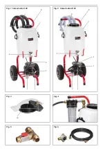
Connect one of the two fabric hoses to the pressure line connection (1). Connect
the 2nd fabric hose to the return line connection (2) of the plastic tank (3).
Connect the respective free end of the pressure or return line to the ball valves
of the solar system and open the ball valves. Close the connecting valve between
the two ball valves of the solar system. Fill the plastic tank (3) with transported
medium and open the ball valve (4). Plug the mains plug of the electrical fi lling
and fl ushing unit into the socket with a protective earth.
CAUTION
CAUTION
Danger of injury due to escaping transported medium. Tighten the hose
screw connections and check for leaks regularly.
2.3. Screw cover with return line connection ¾" and fi ne fi lter bag 70 μm
(accessory art. no. 115220, Fig. 3)
Remove the screw cover (6). Replace the inner plate of the screw cover (6) by
an adapter (10). Screw the screw cover (6) with adapter to the plastic tank.
Insert the fi ne fi lter into the opening in the adapter, screw the screw cover with
¾" return line connection to the adapter, screw the return line to the return line
connection, close the return pipe (2) connection.
2.4. Fine fi lter unit with large dirt collection vessel (accessory art. no. 115323,
Fig. 4)
Fasten the fi ne fi lter unit to the return line connection (2), connect the return
line to the fi ne fi lter unit.
2.5. Changeover valve for alternative suction of the transport medium from
another tank (accessory art. no. 115325, Fig. 5)
Unscrew the line from the plastic tank (3) to the pump at the ball valve (4) and
screw on the changeover valve for alternative suction of the transport medium
at the ball valve (4). Connect one outlet of the T-piece to the pump line, connect
a line to another tank to the other outlet of the T-piece. Control the fl ow direction
with the valve handle.
2.6. Flow direction changeover valve (accessory art. no. 115326, Fig. 6)
The fl ow direction changeover valve serves for clearing deposits/sludge in solar
stations and underfl oor heating. Screw the fl ow direction changeover valve with
connection (P) to the pressure line connection (1). Connect connection (R) of
the fl ow direction changeover valve and the return line connection (2) with the
enclosed ½" T100 EPDM fabric hose. The two "solar station" connections on
the fl ow direction changeover valve are connected to the outlets on the solar
station with the two ½" fabric hoses belonging to the ROLLER’S Solar-Control.
The pressure line and return line to and from the solar station are switched by
turning the lever on the fl ow direction changeover valve with the pump running.
Deposits/sludge are loosened by the generated pressure pulses.
3. Operation
NOTICE
NOTICE
ROLLER’S Solar-Control is not intended/suitable for permanent connection to
the installation. Disconnect all hoses from the installation after completing the
work. ROLLER’S Solar-Control may not be operated unattended.
Do not switch the Solar-Control K 60 pump on until it is fi lled completely with
liquid. Do not allow the pump to run dry! Procedure for fi lling the Solar-Control
K 60: The plastic tank (3) must be fi lled with liquid. The pressure line (1) and
return line (2) must be connected. Open the ball valve (4). Open the bleed
screw (9). Close the bleed screw (9) as soon as liquid emerges.
The pump of the Solar-Control I 80 also sucks dry.
Switch the pump on at the On / Off switch (5). Open and remove the screw
cover (6) on the plastic tank (3) so that the air can escape from the system.
Observe the liquid level in the plastic tank and, if necessary, refi ll with transported
medium so that no air enters the solar circuit. Flush the solar circuit with the
transported medium. At the inspection glass of the fi ne fi lter (7) or by looking
into the large opening of the plastic tank (6), check whether there are still air
bubbles in the transported medium. Continue the fl ushing process until there
is no more air in the transported medium.
Do not close the pressure and return lines of both pumps for longer than 60 s
because the pumps otherwise run hot and will be damaged.
Switch off the pump (5) after the end of the fi lling and fl ushing process. Close
the ball valves on the solar system, open the conneting valve between the two
ball valves of the solar system. Close the ball valve (4). On the ROLLER’S
Solar-Control I 80, reduce the pressure in the pressure line by opening the
pressure relief valve (8). On the ROLLER’S Solar-Control K60, reduce the
pressure in the pressure line by slightly unscrewing the inspection glass on the
fi ne fi lter (7). The pressure relief valve (8) is available as an accessory for the
ROLLER’S Solar-Control K 60.
8
Summary of Contents for Solar-Control I 80
Page 39: ......

