background image

3


Inhaltsverzeichnis 


1


Einbauerklärung 

2


2


Einleitung 

4


3


Normen/ Richtlinien 

4


4


Sicherheitssymbole 

5


5


Anwendung 

6


6


Lagerung 

7


7


Transport 

7


8


Auspacken 

7


9


Geometrische Daten 

8


10


Montagevorbereitung 

9


11


Montage 

10


12


Anschluss Kältemittel 

11


13


Durchbrüche 

12


14


Anschluss Sole 

12


15


Kondensatablauf 

13


16


Befeuchtung 

14


17


Elektroanschluss 

15


18


Schaltplan 

16


19


Ventilatoren 

17


20


Aufsteckmodul 

19


21


Klimaheizungen 

20


22


MS Heizstäbe (Zub.) 

22


23


Inbetriebnahme 

24


24


Schalldaten 

24


25


Reinigung 

25


26


Wartungsintervalle 

26


27


Entsorgung 

26


28


Ersatzteilliste 

26


29


Fehlersuche 

27


Index 


1  Declaration of incorporation  2 
2  Introduction 

3  Standards/ Directives 

4  Safety symbols 

5  Intended application 

6  Storage 

7  Transportation 

8  Unpack 

9  Geometric data 

10 Mounting preparation 

11 Mounting 

10 

12 Refrigerant connection 

11 

13 Cut- outs  

12 

14 Brine connection 

12 

15 Condensate drain 

13 

16 Humidification 

14 

17 Electric connections 

15 

18 Wiring diagram 

16 

19 Fans 

17 

20 Plug- on module (acc.) 

19 

21 AC heaters 

20 

22 MS heater rods (acc.) 

22 

23 Start-up 

24 

24 Sound pressure levels 

24 

25 Cleaning 

25 

26 Service interval 

26 

27 Disposal 

26 

28 Spare parts 

26 

29 Trouble shooting 

27 

Ìndice 


1  Declaración del fabricante  2 
2  Introducción 

3  Normas/ directivas 

4  Símbolos de seguridad 

5  Modos de empleo 

6  Almacenamiento 

7  Transporte 

8  Desembalar 

9  Geometría 

10 Preparación montaje 

11 Montaje 

10 

12 Conexiones de refrigerante  11 
13 Pasos 

12 

14 Conexiones para glicol 

12 

15 Desagüe para condensados13 
16 Humidificador 

14 

17 Conexiones eléctricas 

15 

18 Esquema eléctrico 

16 

19 Motores 

17 

20 Módulo de conexión (acc.)  19 
21 Resistencias calefacción 

20 

22 MS resistencias (acc.) 

22 

23 Puesta en marcha 

24 

24 Datos sonoros 

24 

25 Limpieza 

25 

26 Revisión periódica 

26 

27 Fin del periodo útil  

26 

28 Piezas de repuesto 

26 

29 Diagnóstico de fallos 

27 


Summary of Contents for SV 441 EC

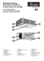
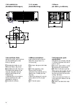
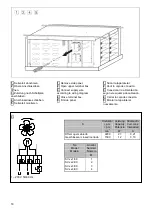
Page 1: ...Ventilator 5 Klimaheizungen 6 Typenschild 7 Befeuchtungseinrichtung 8 Kondensatablauf 1 Side panel 2 Adjustable air outlet jalousie 3 Drain pan 4 Fan 5 AC heaters 6 Type plate 7 Humidification equipme...

Page 2: ...conforme a la Normativa sobre Maquinaria 2006 42 CE Die verwendeten Einzelkomponenten sind konform mit den jeweiligen auf sie zutreffenden folgenden weiteren EG Richtlinien 2006 95 EG Niederspannung 2...

Page 3: ...ant connection 11 13 Cut outs 12 14 Brine connection 12 15 Condensate drain 13 16 Humidification 14 17 Electric connections 15 18 Wiring diagram 16 19 Fans 17 20 Plug on module acc 19 21 AC heaters 20...

Page 4: ...it air coolers are coils with air as secondary fluid according to EN 378 2 paragraph 5 2 1 It fulfills the requirements of EN 14276 2 and paragraph 5 2 2 2 of EN 378 Depending on the type of refrigera...

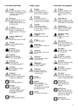
Page 5: ...anger of electric shock Advice for safe transport Attention Cold surfaces Danger of frost bite Attention Hot surfaces Can cause burns Attention Crushing hazard Hand injury possible Attention of flamma...

Page 6: ...to be maintained Position of the type plate see front page Consider the different operating conditions of the fan The following pollutions of the air have to be avoided oAbrasive particles oStrong cor...

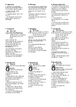
Page 7: ...with intended lifting devices using appropriate fixtures For weight specifications see chapter 9 Move the unit carefully avoiding jolts and impacts Secure the unit against slipping and dropping 8 Unpa...

Page 8: ...mm Rohrinhalte Tube volumes Capacidad de los tubos Gewicht Weights Pesos SV A B C D dm kg 441 EC 678 410 2 0 18 461 EC 678 410 3 0 19 442 EC 1088 820 3 6 28 462 EC 1088 820 5 5 30 443 EC 1498 1230 41...

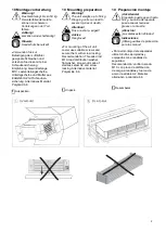
Page 9: ...Attention Fins are sharp edged Advice Use gloves For mounting of the air unit cooler use suitable screws and secure them with screw locking Recommendation Threaded rod M10 load distribution washer fl...

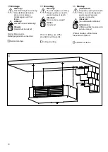
Page 10: ...eighs up to 53 kg Dropping units can lead to severe injuries or death Attention Fins are sharp edged Advice Use gloves When installing use all the provided mounting points 1 Ceiling mounting 11 Montaj...

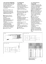
Page 11: ...suction pressure observing its mounting instructions Don t bend or buckle the distributor tubes Connect the refrigerant piping properly Mount the refrigerant piping with enough safety distance to the...

Page 12: ...ack the copper tube in a corrosive way 1 Remove side panel and tube seal 2 Fit the expansion valve observing its mounting instruction Pay attention to the labels which indicate the flow direction Moun...

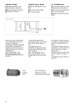
Page 13: ...For heating of the condensate drain a SI heating cable is available as a Roller accessory A too strong tightening of the screw thread can lead to damage and leaks 15 Desag e para condensados Conexion...

Page 14: ...dH eine Entkalkung vor Min Wasserdruck 3 bar Max Wasserdruck 10 bar Wasserdurchsatz je D se bei 3 bar 6 l h To prevent blockage oft he water spray nozzle mount a dirt filter into the water supply on s...

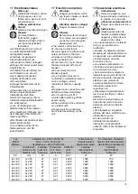
Page 15: ...it till 5 minutes after switching off the power supply When working at the unit stand on a rubber mat Short circuit the conductors and PE before working on the unit 17Conexi nes el ctricas Advertencia...

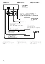
Page 16: ...n to the wiring diagrams for the single components on the following pages Por favor preste atenci n a los diagramas de cableado para los componentes individuales en las p ginas siguientes Steuerleitun...

Page 17: ...has to be checked after installation Depending of the installation it can be necessary to connect another protective conductor to the PE connection at the unit Residual current circuit breaker Exclusi...

Page 18: ...Fit side panel 1 Sacar la tapa lateral 2 Abrir la caja de conexi n 3 Conexionar la alimentaci n seg n el esquema de cableado 4 Cerrar la caja de conexi n 5 Montar la tapa lateral nuevamente 3 1 230 V...

Page 19: ...connector at the fan und remove the connection cable Use a broad flat blade screwdriver Carefully open the control input Plug the modul on Lead the wires to a terminal box Connect the plug on modul ac...

Page 20: ...appropriate distance Perform the risk assessment of the AC heaters Pay attention to the standards EN 378 EN 60204 1 EN 60519 1 2 EN 13849 1 EN 13732 1 and other applicable standards 1 Remove side pan...

Page 21: ...s conexiones son a 230 V E1 E3 Resistencias para calefaccion Termostato de seguridad 1 230 V 50 60 Hz SV 443 464 EC Alle Bauteilspannungen 230 V E1 E3 Heizst be f r Klimaheizung Sicherheitsthermostat...

Page 22: ...er a loss of power Design Heater rods for defrosting Applicable from 50 C to 80 C ambient temperature Protection class IP 66 Connection cable 3 cores approx 1 m length of cable 1 Remove side parts 2 I...

Page 23: ...erencia SV W W 441 EC 3 x 250 750 MS 0440 461 EC 4 x 250 1000 MS 0440 442 EC 3 x 400 1200 MS 0850 462 EC 4 x 400 1600 MS 0850 443 EC 3 x 600 1800 MS 1250 463 EC 4 x 600 2400 MS 1250 444 EC 3 x 850 255...

Page 24: ...e Adjusting expansion valve to superheating tsup 0 5 0 7 x DT1 DT1 12 K DT1 6 K tsup Superheating of the refrigerant at the outlet DT1 Inlet temperature difference Air inlet temperature evaporating te...

Page 25: ...horized and skilled personnel The frequency of cleaning of the air cooler depends on its application A cleaning should be done at least every three months Cleaning of the fan Damage to the fan and mal...

Page 26: ...and dispose them in a correct way When disposing the device please comply with all relevant requirements and regulations applicable in your country 27 Fin del periodo til del evaporador Cuando el apar...

Page 27: ...n blade Hielo en las h lices Fl gel abtauen Defrost fan Quitar el hielo de las h lices Ventilatorbefestigung lose Loose fan fixation Tornillos de fijaci n del ventilador flojos Befestigungsschrauben f...

Page 28: ...nts Reservado el derecho de cambio y de mejoras t cnicas Walter Roller GmbH Co Fabrik f r K lte und Klimager te Lindenstr 27 31 D 70839 Gerlingen Postfach 10 03 30 D 70828 Gerlingen Telefon 0 71 56 20...

Reviews: