background image

2

Rollerdor RD10X2ELL Control Box,  Edition 2022/1

Pictures are for illustration purposes only, connector blocks are not provided and further fittings may be required. 

1. INSTALLING RECEIVER BOX


(SAFETY EDGE)

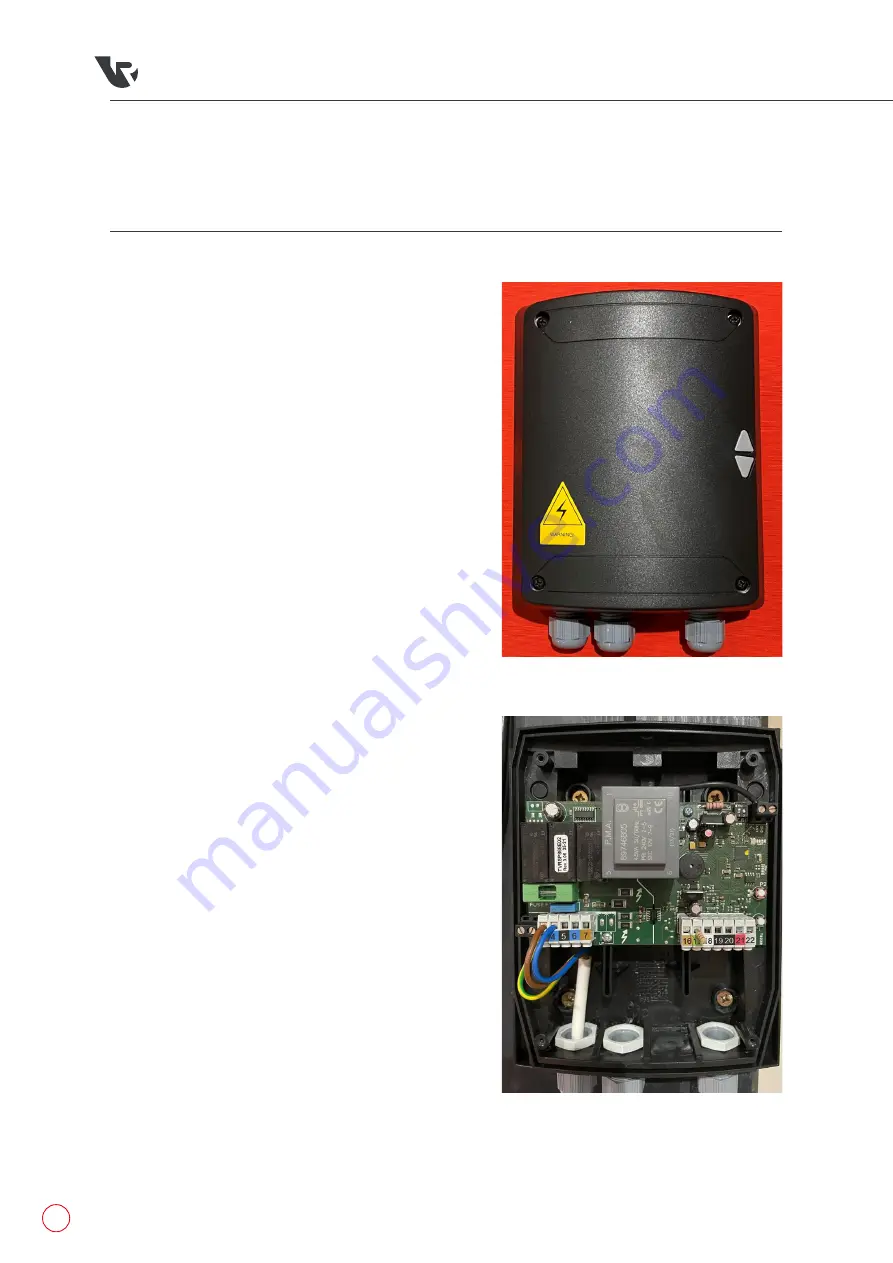
Remove all 4 screws from cover 

(fig.1)

 to reveal 

control board inside 

(fig.2)

.

Place the Receiver box on the wall with the 
cable pointing downwards at a comfortable 
height to operate the push buttons, but out of 
the easy reach of children. Between 1500mm up 
from the floor and 300mm down from the roof/
ceiling is recommended, mark the 4 fixings, drill 
and secure the unit to the wall.

If you have a safety brake with a cable then run 
the two core cable from the safety brake end 
across to the same end as the receiver box, 
making sure to securely fix the cable out of the 
way of the working mechanism.

The Glands at the bottom are for the cables to 
be inserted, (1) motor wire (2) power wire (3) 
safety brake if supplied.

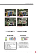
Wiring as follows 

(fig.3, 4 & 5)

:

Terminal 1

 – Earth Motor Wire

Terminal 2

 – Earth Power Wire

Terminal 3

 – Power Brown Live Wire

Terminal 4

 – Power Blue Neutral Wire

Terminal 5

 – Motor Open Wire (left hand 

motor Black / right hand motor Brown)

Terminal 6

 – Motor Blue Neutral Wire

Terminal 7

 – Motor Close wire (left hand 

motor Brown / right hand motor Black)

Terminal 16

 – Safety Edge Brown Wire

Terminal 17

 – Safety Edge Green Wire

Terminal 18

 – Safety Edge White Wire

Safety Brake 

(fig.5 & 6)

:


Terminal 21 - Safety Brake = Blue Safety 
Brake Wire / No safety Brake = Link cable to 
Terminal 22. 

Terminal 22 - Safety Brake = Brown Safety 
Brake Wire / No Safety Brake = Link wire to 
Terminal 21.

fig.2

fig.1

Summary of Contents for RD10X2ELL

Page 1: ...Rollerdor RD10X2ELL Control Box Edition 2022 1 Installation Guide for Roller Garage Doors RD10X2ELL Control Box Edition 2022 1...

Page 2: ...e receiver box making sure to securely fix the cable out of the way of the working mechanism 4 The Glands at the bottom are for the cables to be inserted 1 motor wire 2 power wire 3 safety brake if su...

Page 3: ...tion 2022 1 Pictures are for illustration purposes only connector blocks are not provided and further fittings may be required fig 4 Left Hand Motor fig 5 Safety Brake fig 6 No Safety Brake 2 ELECTRIC...

Page 4: ...1 Control box Dip Switches check dip switches on main board fig 9 dip switch number 1 should be on and number 2 off The control box is supplied in Hold to Run operation for open and close if the limi...

Page 5: ...ers 2 Channel 1 Press P1 PROG button two times on last press HOLD causing the buzzer to emit a continuous sound 2 Whilst P1 PROG is still pressed press the top button on the transmitter you will hear...

Page 6: ...hear a continuous beep from the control box whilst holding the button press and hold Number 1 on the keypad the continuous beep will change to faster beep on hearing this release all buttons and the k...

Page 7: ...ain is supplied with stops at each end to stop an uneven floor having an effect fig 13 but if the curtain reopens having hit the floor the safety edge exclusion should be set to turn off the edge 50mm...

Page 8: ...8 Pictures are for illustration purposes only connector blocks are not provided and further fittings may be required 4 TROUBLESHOOTING...

Page 9: ...orwich Norfolk NR5 9JD 44 0 1603 743215 sales rollerdor net www rollerdor net Company Registration Number 10676267 Registered Office Address Rollerdor Ltd Bankside 300 Peachman Way Broadland Business...

Reviews: