2
Rollerdor RD20X2 Control Box, Edition 2022/1
1. INSTALLING RECEIVER BOX
1
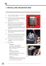
Open the lid of the receiver box by unscrewing the four
screws (one in each corner)
(fig.1)
.
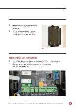
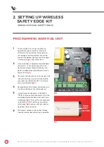
2
Remove the two screws from the bottom of the box (these
can be found behind the glands) and the wall mounting
plate can be removed from the back
(fig.2 & fig.3)
.
3
Making sure the fixing plate is square with the screw
fixings at the bottom, mark the four fixings points. This
should be at a comfortable height to operate the push
buttons but out of the easy reach of children
- between 1500mm from the floor and 300mm down from
the roof/ceiling is recommended. Drill and then secure in
place
(fig.4)
.
4
Hook the top of the receiver box on to the wall fixing plate
with the cable glands pointing downwards and secure
with the two screws.
5
If you have a safety brake with a cable then run the two
core cable from the safety brake end across to the same
end as the receiver box, making sure to securely fix the
cable out of the way of the working mechanism.
6
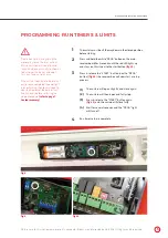
Remove the green 5 terminal block in the bottom left
corner
(fig.5)
and you will see letters printed on the
circuit board.
7
Wiring as follows:
Mains Power:
N
– Neutral / Blue 3 core cable (power)
L
– Live / Brown 3 core cable (power)
Earth
– connect power cable directly to earth from
motor in plastic connector.
Motor:
U
– Brown 4 core cable (motor)
V
– Black 4 core cable (motor)
Earth
- connect motor cable directly to earth from
motor in plastic connector.
W
[c] – Blue 4 core cable (motor)
Safety Brake:
Remove black link wire from far right hand side stop
terminal, and replace with Brown (2 core cable) and
Blue (2 core cable), one each side
(fig.5)
.
fig.1
fig.2
fig.3
Pictures are for illustration purposes only, connector blocks are not provided and further fittings may be required.


