6
Rollerdor RD20X2ELL Control Box, Edition 2022/1
Pictures are for illustration purposes only, connector blocks are not provided and further fittings may be required.
fig.10
CHECKING CONTROL BOX
PROGRAMMING BASE RAIL UNIT
1
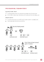
Control box Dip Switches: check dip switches on main board
(fig.11)
dip switch number 1 & 2 should be on
and number 3 off.
2
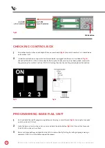
Inside the control box is a separate circuit board which is plugged into the main circuit board
(fig.12)
check the RED LED L3 if this is intermittently flashing then the base rail unit has been paired, move onto
Programming Transmitter’s section, if LED 3 is flashing then continue to Programming Base Rail section.
1
Push and hold the red P1 programming button on the plug in circuit board
(fig.12)
for roughly 2 seconds
until L1 and L2 LED’s flash.
2
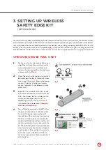
Go to the base rail unit on the curtain, press and hold the white button
(fig.10)
of the unit for 2 seconds.
The RED LED on the unit will flash.
3
Return to the control box and check that the LED L3 is intermittently flashing this will signify programming is
complete, if LED 3 it is still solid then repeat the process.
fig.12
fig.11
White button

