7
Rollerdor RD77 Installation Guide, Edition 2022/01
3. PREPARING GUIDE RUNNERS
FOR INSTALLATION
1
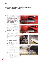
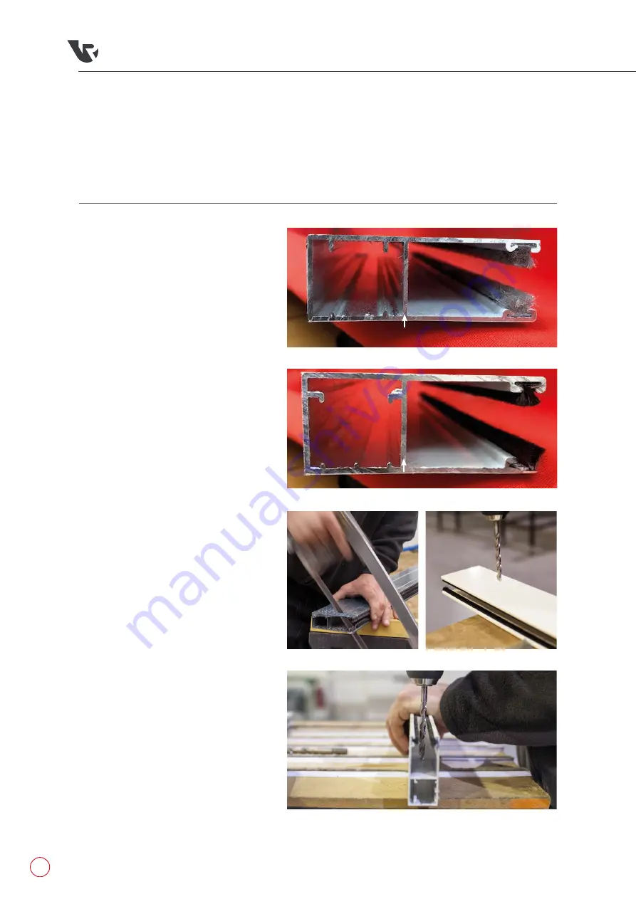
We use 2 types of guide runners
whichever is supplied with your kit will
be marked with the letter ‘F’ to indicate
the front, as seen in
(fig.3.1 type 1)
and
(fig.3.1 type 2)
. This marked face will
fit against the wall for a standard back
fixing or face out of the opening for a
between fixing
(fig.3.5)
.
2
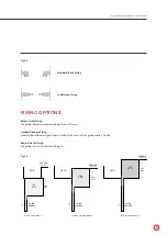
Your guide runners are supplied
oversize and need to be CUT down
to size, check the lintel is level then
measure from floor to lintel both sides
before referring to
(fig3.6)
and making
the cuts as necessary (for best results,
install the guide runners so that the cut
end is against the floor).
3
Offer both cut guide runners up against
the walls they will be fixed to and mark
the fixing points, either on the flat face
for a behind fixing
(fig.3.3)
or for a
between fixing in the opening
(fig.3.4)
.
For best results these should be as
follows;
A
Top fixing between 50mm to
100mm down from the top of the
guide rail.
B
Bottom fixing 50mm to 100mm
up from the floor.
C
Marking as many fixings as
necessary but must be at least
two extra fixings. Spread these
evenly between the two already
marked points on the guide
runners so that you have a secure
fix.
D
Drill a 7mm hole all the way
through each of the marks
and then drill a 10mm hole to
countersink through the first layer
only so you can get the screw
head through.
fig.3.2
fig.3.4
fig.3.3
(fig.3.1 type 1)
Front Face
(fig.3.1 type 2)
Front Face


