background image


Manual No. 4801-6404 Rev 08-12-2013 

PolarCool 

Page 12 of 17 


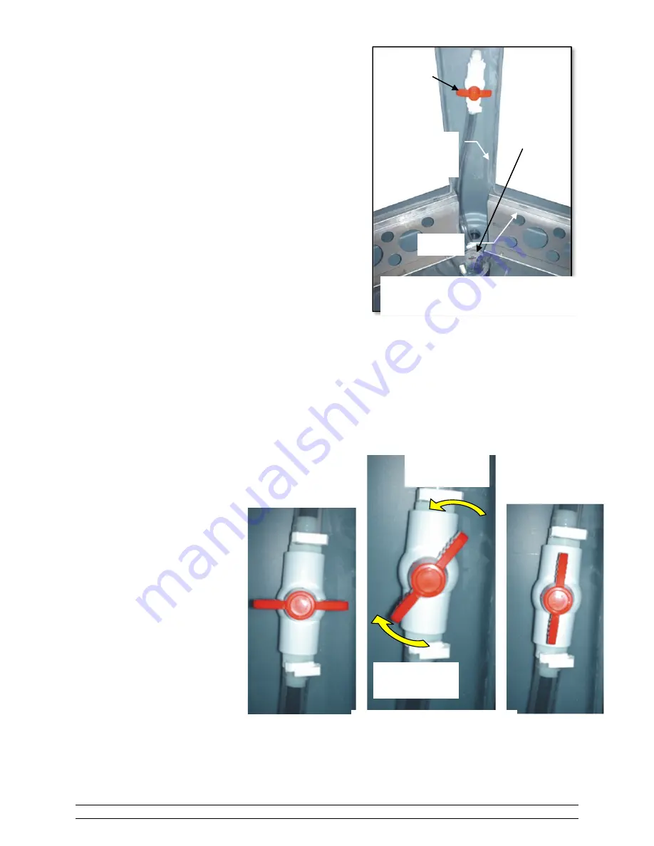
7.9  Flow Control Adjustment 


The Flow Control Valve for the PolarCool Zone is shown to the 
right.  Flow adjustments are factory preset, however can be 
adjusted by the user based upon local water pressure and 
evaporative conditions at the site.  The amount of water flow 
affects the efficiency and operation of the PolarCool Zone.  
During operation the flow should be adjusted so that sufficient 
water soaks the pads, but only enough to completely soak the 
pads. 
 
If there is too much water flow, the pads become over-soaked - 
that is, there is more water flow than required for proper 
evaporation.  Surplus water may be sucked into the fan producing 
a water droplet spray directly in front of the PolarCool.  In some 
cases, if you stand in front of the PolarCool you may feel the 
water spray!  The efficiency of the Polar cool is reduced in this 
case.  If this happens, reduce the water flow. 
 
If there is too little flow, there will not be enough water to fully soak the pads.  Dry spots in the pads will be 
visible.  Again, this reduces the efficiency of the PolarCool.  If this is the case, increase the flow until the pads 
become fully soaked. 
 
Adjust the Water Flow  
as described above.  The 
FULL  
OPEN and CLOSED  
positions of the Valve are  
shown in figures at the right.


Valve 

Closed 

Valve 

Full Open 

Increase 
Pressure 

Adjust Water Flow 

Flow Control Adjustment 

(Pads not shown) 

Flow 

Control 

Valve 

Pump 

Flow 

Control 

Valve 

Pump 

Decrease 
Pressure 

Summary of Contents for PolarCool 36" VS

Page 1: ...Manual No 4801 6404 Rev08 12 2013 PORTABLE EVAPORATIVE COOLING SYSTEM USER S MANUAL Manufactured by PO Box 140 Bremen Alabama 35033 Phone 256 287 7000 Fax 256 287 7010...

Page 2: ...PERATION 8 7 MAINTENANCE 8 7 1 MAINTENANCE ACCESSIBILITY 8 7 2 FREQUENCY OF PAD REPLACEMENT 9 7 3 EXTENDING PAD LIFE 9 7 3 1 Algae 9 7 3 2 Scale 9 7 3 3 Dirt and Dust 9 7 3 4 Why Drain Water From The...

Page 3: ...azardous rotating fan blade Do not place fingers arms or other appendages into the path of the blade or operate the machine without the guards in place Use Caution When Handling Sharp Metal WARNING On...

Page 4: ...ow directed to the attention of Customer Service Manager This limited warranty is expressly in lieu of any and all representations and warranties expressed or implied including any implied warranty of...

Page 5: ...lons 36 VS Direct 12 gallons per hr 8 amps 115v 60hz 11 000 3000 ft 38 Note 1 This estimate is under 90 degree conditions cooler temperatures will result in less water usage Note 2 The cooling area is...

Page 6: ...ton is used to start and stop the water pump Pump ON The green indicator PUMP ON light is ON solid when the water pump is running Low Water The red indicator LOW WATER light is ON blinking when the wa...

Page 7: ...s tripped See Figure A page 8 IF PADS ARE NEW When pads are new their slick surface will prevent the fast water absorption that will happen with older pads For this reason it is important to allow the...

Page 8: ...or is a common way to assure fresh air Evaporative cooling will not function properly in a closed environment 6 2 Normal Operation Under normal conditions the pump should run constantly when air is be...

Page 9: ...s too many impurities Scale formation can be prevented by using water with a pH between 6 and 9 and silica levels below 150 ppm If this is impractical scale can be minimized by increasing the drain of...

Page 10: ...the holes in the spray bar to clear any clogged holes The spray bar end caps may be removed for easier cleaning Ensure the holes in the spray bar point upward during operation 7 4 Flushing the Reservo...

Page 11: ...Use High Pressure Washer To Hose Down Pads 5 Drain the reservoir 6 Shut off pump and clean out strainer 7 Refill reservoir with clean water 8 Replace pads 9 Turn on the pump to run fresh water over t...

Page 12: ...aporation Surplus water may be sucked into the fan producing a water droplet spray directly in front of the PolarCool In some cases if you stand in front of the PolarCool you may feel the water spray...

Page 13: ...ment screw 6 To increase water level in reservoir move float arm upward Retighten arm adjustment screw 7 Replace pads Return PolarCool to operation 8 Repeat steps 1 thru 7 above as required for proper...

Page 14: ...g Guide Problem Check Action Reference Section Swivel casters will not turn Check installation of caster hardware Hardware must be in the proper order and location Water is splashing off of pads Pads...

Page 15: ...Manual No 4801 5035 Rev 08 12 2013 PolarCool Page 15 of 17 11 Wiring Diagram...

Page 16: ...n Cap 0006 0001 Liquid Level Switch 3001 0050 3 Position Connector 3006 5082 2008 and newer models Low Level Switch Harness 3001 0050 2008 and later models Swiveling Caster Tire 1065 0100 Rigid Caster...

Page 17: ...Manual No 4801 6404 Rev 08 12 2013...

Reviews: