Manual No. 4801-5163
Replacement Instructions
Door Assembly PCB154 to PCB201
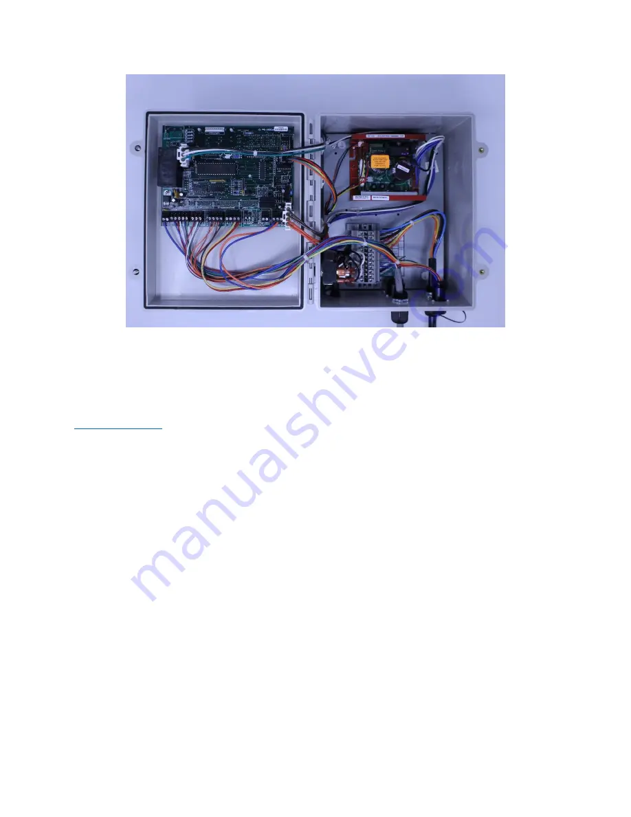
Figure 8: New Door Assembly Installed
Controller Setup:
Once the replacement installation has been concluded, the controller will need to be setup to
match the settings that were noted in a previous step. Refer to the 4801-5156 Controller Manual
for more information involving setup of the controller. This manual can be downloaded from
. The notes that were taken on the provided white label should all be the same
during the setup. There will be several new parameters added and they should be set as
designated on the pre-printed label.
As was previously mentioned, there have been several program parameters added to this new
door assembly and there will be values printed on these parameters that will allow for easy setup.
There has been more capability added to the “P4” setting where the Warning Output can now be
set to sense a fully open/fully closed status with P4=4 and P4=5 respectively. Refer to Figure 9
for more information.


