Part No 4801-5162 Rev 09-2019
RS-500/600 M Series Doors
Page 24
NOTE: The vertical members should be
aligned so that their outer
flanges will exactly overlap with
the framing boards or posts
when the door assembly is raised
into position.
4.
Assemble workers and equipment
into position on each side of the
door assembly.
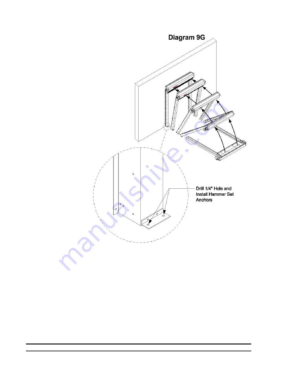
IMPORTANT: SLOWLY LIFT TOP
OF DOOR ASSEMBLY TO
RAISE THE DOOR. See
Diagram 9G.
Diagram 9H
5. Lean door assembly upright against clear opening.
6. Carefully press flanges of the door assembly flush against faces of framing boards or posts.
7. Fasten Tek screws (in steel) or lag screws (in wood) through the flanges on sides of door assembly.
Securely tighten all screws.
8. On the lower and upper flanges of the horizontal member there are attachment points for fastening screws.
Fasten Tek screws (in steel) or lag screws (in wood) through the holes. This secures the top of the door to
the clear opening.
9. On insulated panel applications, Fab-Lok Anchors are provided for outer corners of the head unit and top
and bottom of the track flanges.
9. Locate the two floor mounting holes at the bottom of the left and right tracks.
See Diagram 9H
10. Drill a 1/4" hole and install Hammer Set Anchors (1002-6030) in both right and left tracks. See Diagram
11. This completes fastening of the door assembly to the clear opening.


