CIRCUIT OPERATIONAL DESCRIPTION
9
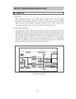
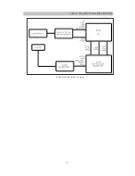
2. DVD Servo AFE IC : ES6603
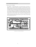
The ES6603 is a high-performance, single-chip analog front-end (AFE) device that
contains the servo functions, RF attenuator, automatic gain controller (AGC), and
programmable equalizer/filter for a DVD player system, and dual auto laser power
control circuit to support twin pickups or twin laser systems.
The ES6603 incorporates a bi-directional serial port for accessing the programmable
functions of the internal AGC, including attenuation and boost/equalization.
The DVD servo block of the ES6603 includes mirror detection, defect detection, dual
auto laser power control, focus error, center error, and tracking error detection
circuits. The ES6603 provides AC-coupled voltage inputs for photo detector signals
used to detect center error, focusing error, tracking error, and differential phase
tracking error detection for DVD.
The ES6603 also provides an AC-coupled differential or single-ended RF signal input
to the programmable attenuator with external AC coupling circuitry, and an AC-
coupled single-ended input for RF signals. The attenuator outputs are AC-coupled to
the AGC inputs. The AC-coupled DVD and CD inputs are multiplexed in the input
stage for accurate error detection.
The programmable bandwidth and boost/equalization of the ES6603 is provided by
internal 7-bit control DACs, while a variable attenuator is used to program the zero
locations. The programmable bandwidth and cutoff range are set by the filter cutoff
DAC. Signal equalization with theprogrammable filter is supported with a wide
bandwidth fullwave rectifier and a dual rate charge pump.
The ES6603 also provides inputs for its internal RF summing mode. These inputs
have the gain control amplifiers at the input stage. The gain is controlled by the
register bit settings of the serial port.
The ES6603 is available in an industry-standard 64-pin low-profile quad flat pack
(LQFP) package.
Summary of Contents for RDV-750
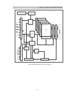
Page 11: ...CIRCUIT OPERATIONAL DESCRIPTION DVD Servo AFE IC ES6603 Block Diagram 10 ...
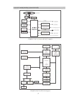
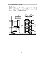
Page 12: ...CIRCUIT OPERATIONAL DESCRIPTION 11 ES6603 ES6629 Block Diagram ...
Page 16: ...HY57V641620HGT H Block Diagram CIRCUIT OPERATIONAL DESCRIPTION 15 ...
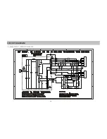
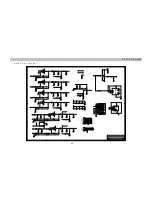
Page 19: ...1 POWER SUPPLY SCHEMATIC DIAGRAM CIRCUIT DIAGRAM 18 ...
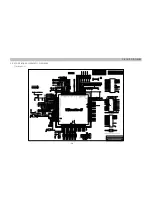
Page 20: ...2 DECODE BOARD SCHEMATIC DIAGRAM CIRCUIT DIAGRAM 1 Vibratto II 19 ...
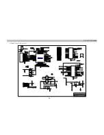
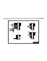
Page 21: ...2 ES6603 and motor drivers CIRCUIT DIAGRAM 20 ...
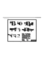
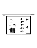
Page 22: ...3 Audio and Power CIRCUIT DIAGRAM 21 ...
Page 23: ...4 Audio filter and output CIRCUIT DIAGRAM 22 ...
Page 24: ...5 Flash SDRAM CIRCUIT DIAGRAM 23 ...
Page 25: ...6 SCART CIRCUIT DIAGRAM 24 ...
Page 26: ...3 CONTROL BOARD SCHEMATIC DIAGRAM CIRCUIT DIAGRAM 25 ...
Page 27: ...4 MICROPHONE BOARD SCHEMATIC DIAGRAM CIRCUIT DIAGRAM 26 ...
Page 28: ...5 YUV BOARD SCHEMATIC DIAGRAM CIRCUIT DIAGRAM 27 ...
Page 29: ...1 POWER SUPPLY BOARD PCB CIRCUIT BOARD 28 ...
Page 30: ...2 DECODE BOARD PCB CIRCUIT BOARD 29 ...
Page 31: ...3 CONTROL BOARD PCB CIRCUIT BOARD 30 ...
Page 32: ...4 MICROPHONE BOARD PCB CIRCUIT BOARD 31 ...
Page 33: ...5 YUV VIDEO OUTPUT BOARD PCB CIRCUIT BOARD 32 ...
Page 35: ...INSTRUMENT DISASSEMBLY 34 Remove three hooks Remove two hooks Simultaneously remove panel ...
Page 38: ...PARTSLIST 37 Unit pcs ...
Page 39: ...38 PARTSLIST ...
Page 40: ...39 PARTSLIST ...
Page 41: ...40 PARTSLIST ...
Page 42: ...41 PARTSLIST ...
Page 43: ...42 PARTSLIST ...
Page 44: ...43 PARTSLIST ...


