32
12.1 AUTOMATIC AiR VALVE
Figure 23.
The cap valve must be loose, not tight, so that the air can come out of the boiler and installations
smoothly.
The boiler must be full with water without air. With the first charging system in the boiler and every year
before the start of the heating season all air from the system needs to be removed.
IN CASE WHERE THE SYSTEM IS EQUIPPED WITH MANUAL AIR VENT:
By FIRST START-UP boiler is vented (as radiators) and wait for the system to work 15-20 minutes
(radiators warm) then re-vent the boiler. After that, venting the system is not necessary as long required
pressure is maintained inside of system. In case when pressure of liquid inside of system drops down
below 0,5 bars it is necessary to recharge and vent the system again as it is done with first starting of
boiler.
WHEN INSTALLED AUTOMATIC AIR VALVE SYSTEM WILL VENT BY ITS SELF.
12.2 EXPANSION VESSEL
The function of the expansion vessel on the heating system is to stabilize the pressure in the boiler and in
the heating installations. The factory preset pressure in the vessel is 1.5 bar if it is not, it is necessary to
adjust it. On the basis of the total amount of water in the heating system and the boiler, it is necessary to
install the appropriate expansion vessel on the system. The size of the vessel according to the rough
estimation makes up 10% of the total amount of water in the heating system and boiler.
In the case where the heating system is greater than defined in the above text, it is necessary to install an
additional or larger expansion bottle for a higher amount of water. The main indicator of an inadequate
expansion vessel is unstable pressure in the heating system.
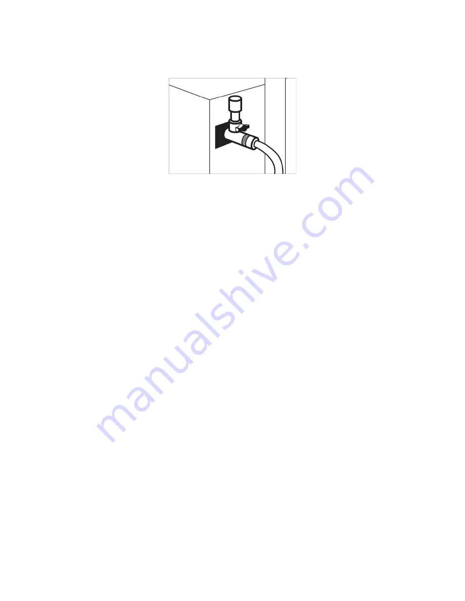
12.3 CHARGING AND DISCHARGING TAP
As the name itself says - this is a tap for charging and discharging. The boiler has an outlet for the
connection, not the particular tap that is purchased separately.
It needs to be installed on the back of the boiler at the bottom. Input connection is recommended to be R1
/ 2 ", while the output should have an extension for the hose.
Summary of Contents for SM ECO 25
Page 7: ...7 Figure 1 Boiler SM ECO 33 compact ...
Page 36: ...36 ...
Page 37: ...37 Figure 28 Power Fan Temperature Fuel Time Settings ...
Page 44: ...44 16 6 ELECTRICITY SCHEME Figure 30 Electricity scheme ...
Page 47: ...47 ...
Page 48: ...48 16 8 ALARMING SITUATION ...
Page 49: ...49 ...
Page 50: ...50 ...
Page 51: ...51 ...


