


15
If the wire guide is too worn or totally clogged, change it to a new one according to the following
instructions.
Open the mounting nut of the wire guide which exposes the end of the wire guide.
Straighten the welding gun’s cable and withdraw the wire guide from the gun.
Push a new wire guide in to the gun. Make sure that the wire guide enters all the way into the
contact tip’s adapter and that there is an O-ring at the machine-end of the guide.
Tighten the wire guide in place with the mounting nut.
Cut the wire guide 2mm from the mounting nut and file the sharp edges of the cut round.
Reattach the gun in place and tighten the parts to spanner tightness.
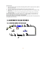
Threading the filler wire
Threading the filler wire as the follow steps:
-
Open the reel housing by pressing on the opening button and install the wire reel in such a
way that it rotates counter clockwise. You can use either a diameter 200mm or 100mm
wire reel in the machine.
-
Attach the reel with a reel lock.
-
Unfasten the wire end from the reel, but hold on it all the time.
-
Straighten the wire end for approximately 20 cm and cut the wire in the straightened
location.
-
Open the pressure control level which then opens the feed gear.
-
Thread the wire through the wire’s rear guide to the gun’s wire guide.
-
Close the feed gear and fasten it with the pressure control lever. Make sure that the wire
runs in the feed roll groove.
-
Adjust the compression pressure with the pressure control lever no higher than to the
middle of the scale. If the pressure is too high, it removes metal fragments from the wire
surface and may damage the wire. On the other hand, if the pressure is too low, the feed
gear slips and the wire does not run smoothly.
-
Press the welding gun trigger and wait for the wire to come out.
-
Close the reel housing cover.
Note: When driving the wire into the gun, do not point the gun at yourself or others.
Summary of Contents for 250MIG
Page 1: ...SERIES 250MIG MIG ...
Page 10: ...10 2 4 Principles of welding ...
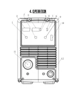
Page 16: ...16 4 OPERATION ...
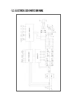
Page 23: ...23 5 3 ELECTRICAL SCHEMATIC DRAWING ...
Page 24: ...24 250MIG MIG ...


