background image

标准化

工艺

批准

日期

设计

制图

校对

审合

处数

标记

更改文件号

重量(g)

日期

签字

上海亿诺科技有限公司

零部件描述

参考编号

材料

公差选择范围

外形尺寸

ICT2098

描   述

图  号

序号

备  注

焊枪15/3米/弹性针/蓝色手柄

-------

上海市顾戴路2535弄99号3号楼2楼

16

图  号

序号

1

2

9

3

6

7

8

11

10

12

13

描   述

数量

备  注

1

2

3

4

7

11

1

2

1

3

1

4

1

5

1

6

1

7

ICS0063

ICU0003-08

ICZ6087

ICV0685

IHQ0070

IFT0874

IHJ0715

IHJ0782

14

IHJ0028

IHJ0645

IFT0063

IZT0071

1

1

1

1

3

1
1

1

1

1

1

1

1

8

17

送丝管锁紧螺母

带绝缘层送丝管0.6-0.8 3米 蓝色

IIC0500

导电嘴 0.8/M6*25

喷嘴 D.12 14-15AK

螺丝 M4X6 UNI 6107

15AK 枪颈(包括六角适配器和塑料适配器)

MIG蓝色手柄

焊枪用开关 21.8mm

螺丝 D.3x10

电缆护套 12-16-25 MMQ

电缆支撑用球节 15AK

手柄锁紧环

二氧化碳欧式后把套

数量

1
1

1

9

18

10

9

5

6

8

塑料适配器

六角适配器

IZH0667

IHJ0030

5

4

1

15

ITB0059

欧式中央插头/弹性针

1

ICG6000

19

导电嘴扳手

1

IHJ0063

焊枪锁紧螺母/塑料螺纹

1

ICN0663

同轴电缆组/16mmq/3米

1

3.1

ICZ0087

15AK 枪颈 

1

3.1


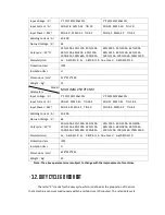
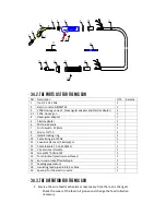
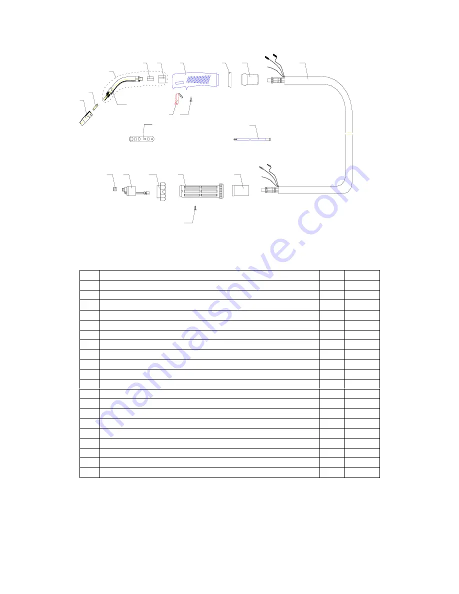
 3.4.2. The parts list for the MIG GUN 

NO.  Description 

QTY. 

Remark 

Tip D.12  14-15AK   


Electric nozzle 0.8/M6*25     


15AK Goose gun neck

Hexangular adapter and Plastic adapter


3.1 

15AK  Goose gun 


Hexangular adapter 


Plastic adapter 


MIG blue handle 


Torch Switch  21.8mm    


Screw  D.3*10          


Handle locking ring 


10 

Cable fixing joint 15AK  


11 

Coaxial cable team /16mmq/3m   


12 

Cable thimble 12-16-25 MMQ   


13 

CO

2

 Euro-rear thimble 


14 

Screw M4*6 UNI 6107   


15 

Torch locknut /plastic screw thread 


16 

Euro-main socket/flexibility pin 


17 

Feeding pipe locknut 


18 

Insulating feed pipe 0.6-0.8 3m, Blue 


19 

Spanner for the electric nozzle 


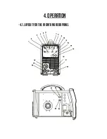
 3.4.3. The operation for the MIG GUN


1.


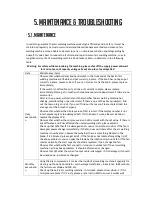
Service the wire feed mechanism at least every time the reel is changed. 

-


Check the wear of the feed roll groove and change the feed roll when 
necessary. 

Summary of Contents for Ronch Weld 200MP

Page 1: ...SERIES 200MP 250MP MULTIPROCESS ...

Page 2: ...IEW 9 2 1 BRIEF INTRODUCTION 9 2 2 WORKING PRINCIPLE 11 2 3 VOLT AMPERE CHARACTERISTIC 12 3 INSTALLATION ADJUSTMENT 13 3 1 PARAMETERS 13 3 2 DUTY CYCLE OVER HEAT 14 3 3 Equipment Connection 14 4 OPERATION 17 4 1 LAYOUT FOR THE Front and Rear PANEL 17 4 2 WELDING Operation 26 4 3 WELDING PARAMETERS 26 4 4 OPERATION ENVIRONMENT 30 ...

Page 3: ...4 5 OPERATION NOTICES 30 5 MAINTENANCE TROUBLESHOOTING 31 5 1 MAINTENANCE 31 5 2 TROUBLESHOOTING 32 5 3 ELECTRICAL Schematic DRAWING 34 ...

Page 4: ...machine power please maintain and examine the equipment according to 5 because of the DC voltage existing in the electrolytic capacitors ELECTRIC SHOCK CAN KILL Never touch electrical parts Wear dry hole free gloves and clothes to insulate yourself Insulate yourself from work and ground using dry insulation Make certain the insulation is large enough to cover your full area of physical contact wit...

Page 5: ...ial ventilation such as stainless or hard facing or on lead or cadmium plated steel and other metals or coatings which produce highly toxic fumes keep exposure as low as possible and below Threshold Limit Values using local exhaust or mechanical ventilation In confined spaces or in some circumstances outdoors a respirator may be required Additional precautions are also required when welding on gal...

Page 6: ...e fire or explosion Remove fire hazards from the welding area If this is not possible cover them to prevent the welding sparks from starting a fire Remember that welding sparks and hot materials from welding can easily go through small cracks and openings to adjacent areas Avoid welding near hydraulic lines Have a fire extinguisher readily available Where compressed gases are to be used at the job...

Page 7: ...e A safe distance from arc welding or cutting operations and any other source of heat sparks or flame Never allow the electrode electrode holder or any other electrically hot parts to touch a cylinder Keep your head and face away from the cylinder valve outlet when opening the cylinder valve Valve protection caps should always be in place and hand tight except when the cylinder is in use or connec...

Page 8: ... Connect the work cable to the workpiece as close as possible to the area being welded The people with heart pacemaker should be away from the welding area 2 OVERVIEW ...

Page 9: ...G MAG 3 Waveform control stable welding arc 4 IGBT technology low power dissipation 5 Rated duty circle is 40 40 MULTIMIG 200 250 has another feature Synergic control of the welding current and voltage MIG SERIES arc welding machine is suitable for all positions welding for various plates made of stainless steel carbon steel alloyed steel copper titanium etc which is also applied to pipe installme...

Page 10: ...olt Ampere Characteristic MIG SERIES welding machine has an excellent volt ampere characteristic whose graph is shown as the following figure The relation between the rated loading voltage U2 and welding current I2 is as follows U2 14 0 05I2 V 44 14 0 600 Io A Uo V Working point Volt ampere characteristic The relation between the rated loading voltage and welding current 2 2 Module Explanation Cur...

Page 11: ...3 Installation ADJUSTMENT 3 1 Parameters Model Parameters MULTIMIG 200 PFC MV ...

Page 12: ...20 130 10 1 220 230 240 10 Input Current A MIG 42 MMA 40 TIG 26 5 MIG 37 MMA 41 TIG 28 5 Input Power KW MIG 4 6 MMA 4 2 TIG 3 0 MIG 8 3 MMA 9 2 TIG 6 4 Welding Current A 40 200 No load Voltage V 65 Duty cycle 40 30 160A 35 130A 35 140A 60 115A 60 100A 60 110A 100 90A 100 80A 100 85A 35 250A 30 250A 35 250A 60 195A 60 180A 60 195A 100 150A 100 140A 100 150A Diameter mm Fe 0 6 0 9 1 0 Ss 0 8 0 9 1 0...

Page 13: ... of wire feeder to the positive output of welding machine 3 Connect the control cable plug of wire feeder to the aero socket on the front board of welding machine 4 Connect the negative pole of welding machine to the work piece base metal 5 Connect the output pipe of gas cylinder to the input joint of gas valve on the wire feeder and clamp it 6 Insert the torch joint into the output of wire feeder...

Page 14: ...缆组 16mmq 3米 1 3 1 ICZ0087 15AK 枪颈 1 3 1 3 4 2 The parts list for the MIG GUN NO Description QTY Remark 1 Tip D 12 14 15AK 1 2 Electric nozzle 0 8 M6 25 1 3 15AK Goose gun neck Hexangular adapter and Plastic adapter 1 3 1 15AK Goose gun 1 4 Hexangular adapter 1 5 Plastic adapter 1 6 MIG blue handle 1 7 Torch Switch 21 8mm 1 8 Screw D 3 10 3 9 Handle locking ring 1 10 Cable fixing joint 15AK 1 11 Co...

Page 15: ...ing gun s parts Tighten the contact tip and contact tip s adapter to spanner tightness 3 Changing the wire guide If the wire guide is too worn or totally clogged change it to a new one according to the following instructions Open the mounting nut of the wire guide which exposes the end of the wire guide Straighten the welding gun s cable and withdraw the wire guide from the gun Push a new wire gui...

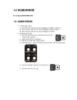
Page 16: ...4 OPERATION 4 1 Layout for the front and rear panel ...

Page 17: ...ob can adjust the current down time On MMA the knob can adjust the force current 9 Power Led Power led is lighted when open the machine 10 Alarm Led When the welder is over voltage less voltage over current or over heated the alarm pilot lamp will be on 11 Wave control knob Controls arc characteristics Determines the rate at which the amperage rises when a short circuit is produced 12 Romote Switc...

Page 18: ...ielding gas is 98 Ar 2 O2 3 When the wire material is Al the shielding gas is 100 Ar 2 Welding state choice 1 Press the weld manner key choose MIG manner and the MIG LED is lighted 2 Spool Gun Switch turn off down 3 Manual wire switch air check switch 4 Burnback adjust Slow feed adjust Post flow adjust Pre flow knob adjust 5 Press the welding mode key choose 2T or 4T 6 Spool Gun Switch turn on up ...

Page 19: ...e operation 1 Press the weld manner key choose TIG manner and the TIG LED is lighted 2 Press the welding mode key choose 2T or 4T 3 Adjust the current knob to control the welding current 4 Adjust the down slope knob to control the welding current descend time 4 2 3 MMA mode operation 1 Press the weld manner key choose MMA manner and the MMA LED is lighted 2 Adjust the current knob to control the w...

Page 20: ...re that there is sufficient ventilation during welding There is at least 30cm free distance between the machine and wall 4 5 Operation Notices Read 1 carefully before attempting to use this equipment Connect the ground wire with the machine directly and refer to 3 5 Ensure that the input is single phase 50 60Hz 110V 220V 10 Before operation no concerned people should be left Do not watch the arc i...

Page 21: ...reason Please contact local this area agent or the branch company Observe that whether the display value of LED is intact If the display number is not intact please replace the damaged LED If it still doesn t work please maintain or replace the display PCB Observe that whether the min max value on LED accords with the set value If there is any difference and it has affected the normal welding craf...

Page 22: ...is authorized by our company could overhaul the machine Guarantee to shut off the arc welding machine s power before turn on the outline of the equipment If there is any problem and has no the authorized professional maintenance personal of our company please contact our local agent or the branch company If there are some simple troubles of MIG SERIES welding machine you can consult the following ...

Page 23: ... No striking arc and no output voltage Output cable is connected mistakenly or loosen Screw it down or change it Control circuit damaged Check the circuit 6 Welding stops and alarm light is on Machine has self protection Check over voltage over current over temperature lower voltage and over temperature and solve it 7 Welding current is run away and can be not controlled The potentiometer damaged ...

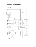
Page 24: ... 5 3 Electrical Schematic drawing ...

Page 25: ...25 200MP 250MP MULTIPROCESS ...

Reviews: