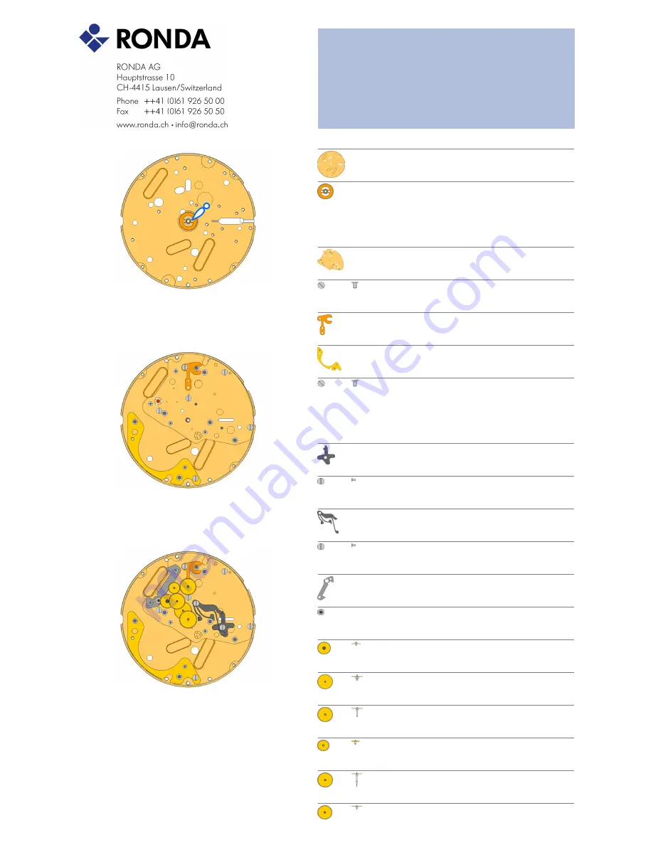
Technical Instructions 7004.N
Assembling
16 Mar 2010
2
2000.669.G
Main Plate
1.
Use Moebius 9014 on bearing of all rubis
3305.329
Cannon pinion with driver B (Aig. 1)
2.
Moebius 8200 greace must be placed between the steel tube and the
wheel. The steel tube must be placed into the center hole of the main
plate.
A
2030.028.CO
Centre Bridge
3.
Use 3 screws 4000.250.
4000.250
Screws
4.
B
3406.039
Sliding attachement
5.
Use 1 screw 4000.250.
2130.181
Combined maintaining plate
6.
Use 1 screw 4000.250.
4000.250
Screw
7.
3016.028
Lever for setting lever
8.
"If the stem and the mechanism is already placed on the backside,
place the stem into the middle position. Then use 1 screw 4000.249 to
fix the lever for setting lever."
4000.249
Screw
9.
3016.027
Stop lever
10.
Position the Stop lever under the ?Lever for setting lever? and fix the
Stop lever by using 1 screw 4000.249. The reset arm of the Stop lever
must be placed according to the picture. Use Moebius 8200 at the
contact point of the 2 levers.
4000.249
Screw
11.
3622.044
Stator
12.
3715.105.RK
Rotor
13.
Use an antimagnetic tweezers to place the rotor.
3147.060.CO
Intermediate wheel
14.
3122.062.CO
Third wheel
15.
3136.174.CO
Centre second wheel (Aig. 1)
16.
3004.203.CO
Seconde intermediate wheel
17.
3136.182.CO
Small second wheel axle
18.
3136.173.CO
Centre second wheel (Aig. 1)
19.
C


