NEXUS CALL SYSTEM
by Rondish
P25
8
N/A
924.6
919
9
N/A
925
910
A
N/A
919.63
910
B
N/A
919.72
910
C
N/A
919.75
910
D
N/A
919.83
910
E
N/A
919.87
910
F
N/A
919.92
910
2.2.3 Target Address
If the ZP-01(S) is set to signal the ZP-01(M) this should be
set to “48” (i.e. = the address set during
3.6.4).
To program this,
1.
Adjust the rotary switch to “4” and press the T
-SW button,
2.
Adjust the rotary to “8” and press T
-SW again.
3.
The Tx/Rx LED will then come back on and stay on “steady” briefly to indicate “programming
finished”.
4.
The ZP-01(S) then automatically exits programming mode, reboots itself and returns to normal
operating mode.
If you are programming a signal “hop”, the target address should
instead be the ZPID of the ZP-01(S)
where you will relay the signal (See Section 2.2.6).
2.2.4 Data Rate
Make sure to set this to ‘0’ for Nexus 2.0 and higher
2.2.5 Repeater Address
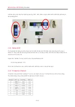
This tells the ZP-01(M) where to find this particular repeater. The ZP-01(S) address (0-47) must be unique
within the system so it can be individually called by the Master and Call Points.
The ZP-01(S) unique address is set by adjusting the rotary and DIP switches shown at
“Address” in the
picture in Section 2.2 above. This setting can be selected without entering programming. When this is
changed the ZP-01(S) should be turned off and then back on before the Repeater Address will be
registered by the Master unit with the new ZPID.
The RSSI value of the connection to the ZP-01(M) will be recorded in the Event Log, which will help
installers determine whether a call point has a strong enough connection. Rondish recommends a value
of >100 to ensure a reliable wireless network.

