background image


11 


4.

 If you suspect the spray tip or hose is clogged or that pressure has not been fully relieved after following the steps above, 

VERY SLOWLY loosen tip guard retaining nut or hose end coupling to relieve pressure gradually, then loosen completely. 

Clear hose or tip obstruction.


5.Engage trigger safety lock on gun if unit is being shut down or left unattended. 

Opearating Instructions   

BEFORE STARTING 


(1)CHECK 

all fittings and connections in the pump system, hose, and gun to ensure that they are 

tight.   

CHECK 

to ensure that there is a spray tip in the gun, and that the tip is the correct size for the coating 

you are to spray. (There are various tips available, for each type of coating or configuration.) 

(2) MAKE SURE 

the power source is securely grounded and match the motor rating of your sprayer. 

(3) New spray

: Oil is used by the factory for testing and protection. It is necessary to flush unit before 

spraying. Clean the pump with warm soapy water, Make sure the hydraulic oil in the pump is clean 
and sufficient in volume then begin the following procedure 

1

. Remove spray tip from gun   

2

. Put the input hose and pressure relief tube into the bucket with some water, 

3

. Turn on the motor and push the pressure valve upright. In a few seconds, water will begin to flow up through the 

tube and flow out from outlet valve, tighten the outlet valve deasil, then tighten the pressure valve deasil. 

4

. When the pressure reaches up to around 227bar, check if there is any leakage on the outlet hose, if it

’s leak, 

Please check. 

Don’t stop or deflect leaks with your hand, body, glove or rag. 

5

. If does

n’t leak, open the spray gun and have a testing spray. Clean the oil in pump. Change the soapy water and 

use clean water when the spray is clean 

6

. Turn off power, Continue to spray till no water out. 

7

. Unlock trigger lock. Put the pressure valve upright, till no soapy water in pump   

Operation 

Setup 


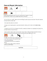
WARNING


Make sure sparayer is turned off and unplugged from power source. 

Connect Gun to Sprayer 

1.  Connect supply hose to sprayer fluid outlet. 

2.  Connect other end of supply hose to gun swivel. Use wrenches to tighten all connections securely. 

Installing tip and guard on gun 


WARNING


Summary of Contents for R470 220V

Page 1: ...oatings Contents 1 Must be grounded Read Grounding instructions Use only grounded electrical outlets or Ground equipment and conductive objects in work area 2 Have heart problem or with heart pacemake...

Page 2: ...4 Paint or solvent flowing through the equipment is able to result in static electricity Static electricity creates a risk of fire or explosion in the presence of paint or solvent fumes All parts of t...

Page 3: ...painting 2 Do not operate or spray near children Keep children away from equipment at all times 3 Don not overreach or stand on an unstable support Keep effective footing and balance at all times 4 St...

Page 4: ...when flammable fumes are present Ground equipment and conductive objects in work area Read Grounding instructions If there is static sparking or you feel a shock stop operation immediately Do not use...

Page 5: ...oses to pull equipment Comply with all applicable safety regulations Keep children and animals away from work area Do not operate the equipment when fatigued or under the influence of drugs or alcohol...

Page 6: ...d reminding the user to be aware of the recommendations of the coating material manufacturer D Surface temperatures of any part of the machine reachable during normal operation maintenance and servici...

Page 7: ...be plugged into an outlet that is properly installed and Number Description Function Introduction 01 Pressure Adjust Knob Control output pressure of Paint Clockwise increase pressure anticlockwise de...

Page 8: ...ith an appropriate grounding contact Never use an outlet that is not grounded or an adapter Do not use the sprayer if the electrical cord has a damaged ground contact Only use an extension cord with a...

Page 9: ...the Spray Gun Always lock the trigger off when attaching the spray tip or when thr spray gun is not in use Locking the Spray Gun Unlocking the Spray Gun The gun is secured when To unlock the gun turn...

Page 10: ...een the braid layers FEATURES Polyurethane cover permits greater flexibility and tighter bends Resistant to flex fatigue Dissipates static charge Will not swell or degrade in contact with most paint c...

Page 11: ...the pump is clean and sufficient in volume then begin the following procedure 1 Remove spray tip from gun 2 Put the input hose and pressure relief tube into the bucket with some water 3 Turn on the mo...

Page 12: ...l has been removed from under the cap on the hydraulic tank Hydraulic tank should be at least 3 4 full of hydraulic fluid 1 During paint spraying hold the gun upright to the surface of paint object an...

Page 13: ...raying Check or service equipment or install or clean spray tip 1 Engage trigger safety lock on gun Turn Off power and turn sprayer pressure control to lowest pressure setting 2 Hold gun against side...

Page 14: ...enever you service sprayer Do not operate the sprayer without the motor shroud in place Replace if damaged Motor shroud directs cooling air around motor to prevent overheating and insulates the contro...

Page 15: ...warm area to thaw Do not start sprayer until thawed completely If paint hardened dried in sprayer replace pump packings 2 Displacement pump connecting rod pin Pin must be completely pushed into connec...

Page 16: ...rbon dust by using compressed air to blow out brush dust 10 Low stall pressure Turn pressure control knob fully clockwise 10 Replace pressure control assembly 11 Motor armature for shorts by using an...

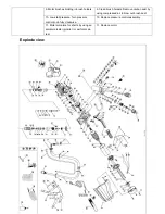
Page 17: ...ly 1 113 Filter element 1 15 The little ring 1 65 Single row radial ball bearing 1 114 O Rings 24 3X1 8 1 16 Discharge joint 2 66 Motor stator components 1 115 A filter element knob 1 17 Pump body 1 6...

Page 18: ...spray gun 1 41 Cross Recess Head Screw 10 91 Hexagon socket cap screws 1 139 description 1 42 Pump body cover 1 92 Transporting pipe components 1 140 High voltage paint 7 6m black 1 43 Dust Stop block...

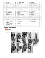
Page 19: ...take out the ring size 6 In the size of ring outer ring with a little grease Press the ring into the pump body 7 Press the plunger rod into the pump body 8 Put Into the pump body components according...

Page 20: ...20 1 Left Secondary Frame With Handle Grip 1PCS 2 Right Secondary Frame With Handle Grip 1PCS 3 White Seal Washer 3PCS 4 Black Seal Washer 2PCS...

Reviews: