12
RONK Automatic Transfer Switch Owner’s Manual
INSTALLATION & WIRING
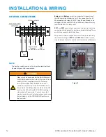
CONTROL CONNECTIONS
Figure 6
NOTE:
The transfer switch consists of the 6-position terminal block
(shown in Figure 6) for connections.
Transfer Switch
(Internal)
+ -
N.O. dry contacts
Remote Start
Contact
(To Generator)
BATT +
BATT
-
RSC1
RSC2
TEST1
TEST2
SPST
(Optional)
B and Battery – must be connected for operation of
the DSE controller. Standard is for 12 Vdc connection. For 24
Vdc operation, the relays K1, K2, K3, and K4 would need to be
changed to 24 Vdc coils. K3 & K4 on 600A only. Consult factory
for kit RONK 26097 (2 relay coils).
RSC1 and RSC2 need to be connected to the remote start/stop
connections of the generator to allow automatic starting. These
are N.O. dry contacts. 8A, 35 Vdc Max.
An optional customer-supplied test switch may be installed by
the customer using the
TEST 1 and TEST 2 terminals. A closed
circuit between the test connections will simulate a utility failure.
Figure 7
!
WARNING
Make sure the disconnects for the LINE (Utility) and
AUXILIARY (Generator) are in the OFF position. Once
battery (12 Vdc) is applied to the ATS customer
terminal block ( & BATTERY-) the ATS
controller will power up to the AUTO MODE. Since
the power to the LINE position should be in the OFF
position, the ATS will close RSC1 & RSC2 sending a
start signal to the generator. To avoid injury that
may be caused by such a start-up, please make sure
the generator is in the OFF/DISABLED position on
the controller.
Summary of Contents for 100-600 AMP
Page 1: ...OWNER S INSTALLATION MANUAL 100 600 AMP RONK Automatic Transfer Switch...
Page 30: ...30 RONK Automatic Transfer Switch Owner s Manual NOTES...
Page 31: ...RONK Automatic Transfer Switch Owner s Manual 31...
Page 32: ...106 E State Street Nokomis IL 62075 800 221 7665 www ronkelectrical com...

