Ronk Vigilant
®
Owner’s and Installation Manual
15
ADJUSTMENTS AND SETTINGS
System Adjustments
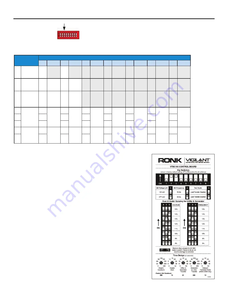
Table 2: Dip Switch Settings
Feature
Switch Settings
Set
Function
Set
Function
Set
Function
Set
Function
Set
Function
Set
Function
Set
Function
1
Keep in OFF
position at
all times
OFF
–
OFF
–
–
–
–
–
–
–
–
–
–
–
2*
Set the unit
for 50/60Hz
systems
ON
60 Hz
OFF
50 Hz
–
–
–
–
–
–
–
–
–
–
3*
Weekly
exercise
with load/no
load
ON
Load
test
cycle
OFF
No load
test
cycle
–
–
–
–
–
–
–
–
–
–
4
Set the
over/under
voltage
setting
OFF
Dropout
v 18%
Pickup v
13%
OFF Dropout
v 17%
Pickup v
12%
OFF
Dropout
v 16%
Pickup v
11%
OFF Dropout
v 15%
Pickup v
10%
ON
Dropout
v 14%
Pickup v
9%
ON
Dropout
v 13%
Pickup v
8%
ON
Dropout
v 12%
Pickup v
7%
5
OFF
OFF
ON
ON
OFF
OFF
ON
6
OFF
ON
OFF
ON
OFF
ON
OFF
7
Set the
over/under
frequency
setting
OFF
12%
OFF
11%
OFF
10%
OFF
9%
ON
8%
ON
7%
ON
6%
8
OFF
OFF
ON
ON
OFF
OFF
ON
No Function: Switch #1
The dip switch #1 should remain in the off position at all times.
50/60 HZ: Switch #2
The dip switch located on the control board is used to set the unit for 50 or 60 Hz systems.
When switch location #2 is on, the system is configured for 60 Hz. When switch location
#2 is off, the unit is configured for 50 Hz systems.
Load/No Load: Switch #3
The dip switch located on the control board may be used for load/no-load exerciser testing.
When switch location #3 is on, the system is configured for a load test condition allowing
transfer to a generator power source. When switch location #3 is off, the unit is configured
for a no-load test condition with no transfer to a generator power source.
This setting applies to the engine exerciser test only.
Under/Over Voltage: Switch #4, 5, 6
The dip switch located on the control board may be used to set the Over/Under voltage
setting. Depending upon the positions of dip switch locations 4, 5 and 6, the control board
will determine the percentage range to recognize a utility failure. The failure percentage
adjustments can range from 11 to 18 percent of the utility power source for dropout and
6 to13 percent for pickup. Switch 4, 5 and 6 off for 18% and on for 11% dropout.
Under/Over Frequency: Switch #7, 8, 9
The dip switch located on the control board is used to set the Over/Under frequency setting.
Depending upon the positions of dip switch locations 7, 8 and 9, the control board will
determine the percentage range to recognize a utility failure. The failure percentage
adjustments can range from 5 to 12 percent of the utility power source. Switch 7, 8 and 9
off for 12% and on for 5% range.


