background image

34

MACHINE OPERATION

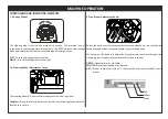
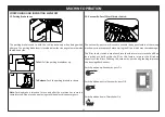
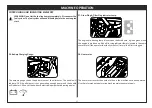
The headlamp switch is used to ac vate the headlamps and the taillamps 
of the machine.

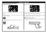
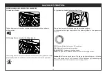
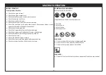
The warning beacon lamp switch is used to ac vate the warning beacon lamps 
(if equipped) which are used to warn others that the machine is in opera on.

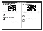
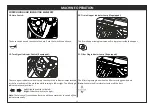
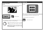
The igni on key switch starts and stops the machine’s engine.
It  is  located  at  the  right  hand  side  of  the  steering  wheel  in  the  operator’s 
console.

15. Headlamp Switch:

16. Warning Beacon Lamp Switch (if equipped):

17. Igni on Key Switch for Engine Start/Stop:

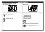
GL

ON

OFF

OFF -

 Engine & Electrical’s are in Off condi on.

ON -

 Electrical systems are powered up.

PRE-HEAT (GL) -

 Engine pre-hea ng begins.

START -

 Engine starts. Release the key as soon as the engine starts.

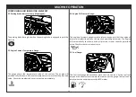
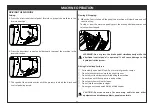
Preheat (GL):

 Turn the key clockwise. The glow plug light will come on. Hold the 

key in this posi on for 15 to 30 seconds ( ll the light goes off), depending on 
weather condi ons. Colder weather requires longer  me.

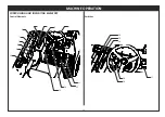
CONTROLLING AND INDICATING ELEMENTS

Summary of Contents for RHINO RD 160

Page 1: ...1 OWNER S MANUAL ILLUSTRATED PARTS LIST Readthismanualcompletelyandunderstand theinstruc onsbeforeopera ngthemachine EnglishVersion OriginalInstruc ons Ride On Sweeper Diesel...

Page 2: ...2 BLANK...

Page 3: ...ce Model No _______________________________ Serial No ________________________________ Engine Serial No __________________________ Accessories ______________________________ Sales Rep ________________...

Page 4: ...4 INTRODUCTION 4...

Page 5: ...lved The appropriate Accident Prevention Regulations as well as applicable general regulations pertaining to Safety and Health at the work place must be adhered to by the user Modifications made to ma...

Page 6: ...6 INTRODUCTION Prior to first operation read the manual s carefully and strictly comply with theinstructionscontained The Owner s Manual is an integral part of the machine and must not be misplaced...

Page 7: ...7 TECHNICAL SPECIFICATION...

Page 8: ...UNIT VALUE LENGTH Opera on Shipping mm 2686 2694 WIDTH Opera on Shipping mm 1590 1905 HEIGHT Top of air cleaner mm 1665 HEIGHT WITH OVERHEAD GUARD mm 2320 HEIGHT Shipping mm 1842 GVWR kg 1800 NORMAL S...

Page 9: ...9 KNOW YOUR MACHINE...

Page 10: ...adlamps 7 Debrishopperwith lters andshakerassembly 8 Machinecontrols 9 Rightsidemainbroomaccessdoor 10 Taillamps 11 Fueltankandhydraulicoiltank 12 Electricalaccesspanel 13 Sidebroom 14 Mainbroom 15 Ov...

Page 11: ...11 SAFETY INSTRUCTIONS...

Page 12: ...pment must be checked to ensure that it is in proper working order and is opera ng safely prior to use Otherwise the machinemustnotbeused The machine is not suitable for sweeping dust which endangers...

Page 13: ...immediate vicinity prior to star ng e g children Ensure su cientvisibility l The machine may only be used by persons who have been instructed in handling the machine or have proven quali ca on and ex...

Page 14: ...sesarepoisonousandhazardoustohealth donotinhalethem Read the opera ng instruc ons of the engine manufacturer before start up andfollowthesafetyinstruc onscarefully Riskofexplosion Pneuma c Tires Equip...

Page 15: ...15 STICKERS ON THE MACHINE...

Page 16: ...16 STICKERS ON THE MACHINE Branding Labels 2 3 1 1 Product category s cker 2 Manufacturer s logo s cker 3 Product name s cker...

Page 17: ...SB OFF 1 6 9 7 8 3 4 5 2 1 Main Side broom indicator s cker 2 Hopper control s cker 3 Igni on coil Hydraulic oil lter clog indicator 4 Ba ery charging s cker 5 Turn signal indicator s cker 6 Switch p...

Page 18: ...N THE MACHINE 1 Hopper li arm safety warning s cker 2 Rota ng fan keep away safety s cker 3 Rota ng belt keep away safety s cker 4 Diesel fuel safety s cker 5 Ba ery loca on warning s cker 6 Machine s...

Page 19: ...ns with compressed air If so equipped Wheels and tires Check and tighten front rear wheel nuts to 200 Nm torque For the first time only Main Broom Hydraulic system MAINTENANCE AREA THINGS TO CHECK Cle...

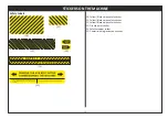
Page 20: ...13 14 15 STICKERS ON THE MACHINE 10 Yellow Black stripe safety s cker 11 Yellow Black stripe safety s cker 12 Yellow Black stripe safety s cker 13 Grease point s cker 14 Safety stopper s cker 15 Commi...

Page 21: ...21 MACHINE OPERATION...

Page 22: ...ntentsofthismanual Donotusethismachinetocollectanyhazardousdebris Donotusethismachineasatransportequipment WARNING Do not use this machine on surfaces exceeding a maximum of thegivenvalueforthegradien...

Page 23: ...toolsandsafetydevices Upon Unloading l Check the machine for any transit damage such as dents paint damage scratches leaks etc l Checkcoolantlevelintheradiator l Checktheengineoillevel l Checkthehydra...

Page 24: ...kesuretheareatobesweptisdry Position the machine in the direction that the wind blows the dust away fromthemachine For optimum cleaning results match the driving speed with the area to be swept Switch...

Page 25: ...25 MACHINE OPERATION CONTROLLING AND INDICATING ELEMENTS Control Elements 1 2 3 4 5 10 6 7 8 9 11 12 13 1 a 14 15 16 17 18 19 Switches...

Page 26: ...l 13 Parkingbrakelever 14 VacuumBy Pass Filtervibratoron o switch 15 Headlampswitch 16 Warningbeaconlampon o switch ifequipped 17 Igni onkeyswitchforengine 18 Hornswitch 19 Turnsignalindicatorswitch 2...

Page 27: ...e knob counter clockwise to release the mechanism move the knob tothedesiredposi on rotateclockwisetosecuretheposi on Thepurposeofthisknobistoadjustthebrushpressuretoachievetherequired cleaningintensi...

Page 28: ...EEP 4 Main Broom Adjustment Knob Rotate the knob counter clockwise to release the mechanism move the knob tothedesiredposi on rotateclockwisetosecuretheposi on Thepurposeofthisknobistoadjustthebrushpr...

Page 29: ...console Leverposi onforward Todeploy lower themainbroompushthelever Leverposi onbackward Tostore raise themainbroompullthelever Float posi on In this posi on the main broom oats above the sweeping su...

Page 30: ...is DCS move the debris lying near the entrance of the door to the innerendofthehopper Leverposi onle ward DCScompactmode Leverposi onrightward DCSO Returntosweepmode DOOR MACHINE OPERATION 7 Hopper Do...

Page 31: ...The engine speed can be controlled via a thro le lever assembly located in the operator s console The lever is notched to set the required engine speed duringthemachine sopera on 10 Thro le Lever The...

Page 32: ...ofyourfoot To Stop Take your foot o the direc onal control pedal and let it return to the neutral posi on Steponthebrakepedal Reverse Press the bo om of the direc onal pedalwiththeheelofyourfoot Note...

Page 33: ...shake o ne dust which are held within the lter this feature improves the ltra on capacity of the lters Shu ng the vacuum by pass during shaking improves thecleaninge ec veness Switchposi onup Vacuumby...

Page 34: ...operator s console 15 Headlamp Switch 16 Warning Beacon Lamp Switch if equipped 17 Igni on Key Switch for Engine Start Stop G L ON OFF OFF Engine Electrical s are in O condi on ON Electrical systems a...

Page 35: ...ted at the front and rear of the machine while turning to le or right The blinking is indicatedintheswitchitself The ltercloglampglowswhenthe ltersarecloggedwithdust Note Ac vatethe ltervibratortoclea...

Page 36: ...Temperature Gauge The engine oil pressure gauge is used to inform the operator that the engine oil pressure is higher lower than the required opera ng parameter The engine will automa cally shut down...

Page 37: ...30ifanyoftheon boardelectricalequipmentisdrawingpower The hourmeter records the number of hours the machine has been operated Usethisinforma ontodeterminemachinemaintenanceintervals The engine pre hea...

Page 38: ...remove the seat belt while the machineisinmo on The operator seat can be adjusted forward or backward to suite the user s height Ithastwofoldablearmrestsandaseatbelt ifequipped Operator Seat CONTROLL...

Page 39: ...ern Checkthehopperdust lterforblocksordamage Checkthehoppersealsandgasketsforwearanddamage Checkthebrakesandsteeringforproperopera on Checkthefuellevel Checkifthedebrishopperisempty Checktheairpressur...

Page 40: ...OFF NOTE If the engine does not start after 10 seconds release key wait for 1 minute and repeat the procedure again NOTE If engine does not start in the first crank do not continue cranking open hood...

Page 41: ...ly press the brake pedal downwards and releasewhenstopped Slowing Stopping WARNING Do not press the brake pedal simultaneously while the directional control pedal is operated It will cause damage to t...

Page 42: ...l Work Lamps DRIVING THE MACHINE Headlamps Rear work lamp op onal w OHG Front Rear work lamp with OHG op onal Front work lamp op onal w OHG NOTE Switch Off the headlamps and work lamps when not in use...

Page 43: ...resweeping Fla enorremovebulkycartonsfrom aisles before sweeping Pick up pieces of wire ropes string etc which could becomeentangledinbrooms Plan the sweeping in advance Try to work in long runs with...

Page 44: ...ine speed For normal at surfaces Higher engine speed For sweeping on inclined surfaces SWEEPING 3 Lowerthemainbroomandsidebroom Releasetheleverfromthenotchandpushitforwardtolowerthemainbroom Release t...

Page 45: ...onwhensweepingawetsurfaceisbeingswept Do not sweep or vacuum Corrosive Battery Fluids Explosive Flammable Magnetic Radioactive Biohazard materials SWEEPING 6 Ac vate the Debris Compact System DCS lev...

Page 46: ...vate the lter shaker to shake o remaining debris and dust from the panel lter MB ON SB OFF NOTE The lter shaker switch is of a momentary type hold down ll required releasetoswitcho NOTE If a mer kit i...

Page 47: ...afety Stopper The safety stopper is a device used to prevent the hopper from falling down whilecleaningorduringmaintenanceworks 1 Engageparkingbrake 2 Starttheengine 3 Li hopperupcompletely 4 Releaset...

Page 48: ...kinitsstorageposi on 6 Lowerthehopper 7 Switcho theengineandremovekey ALWAYS NEVER Whilesweepingorpassingaramp alwaysdrivethemachine withitsfrontsidefacinguphill Neverdrivethemachinedownhillwithafullh...

Page 49: ...sbelow CAUTION Filter chamber door care should be taken while opening or closing Pinchhazard WARNING ENSURE THAT THE ENGINE IS SHUT DOWN BEFORE CLEANINGTHEDUSTFILTERS Lever 2 Usethelatchestoremovethe...

Page 50: ...50 MAINTENANCE...

Page 51: ...l Tank The hydraulic oil tank is located below the operator seat The hydraulic pump is located in the engine bay attached to the engine The hydraulic oil tank has a cap with a breather assembly Check...

Page 52: ...draulicoil Ifanyoilleakhasbeendetectedcontactaftersalesservice The hydraulic drive motor should be checked for leaks Repair the hose fittings orotherpartsifanydamageisnoted Refusingtodosomaydamagethem...

Page 53: ...ngine crankshaft pulley which also drives the alternator pulley have to be checked for wear and tear The belts also have tobecheckedforthecorrecttensionsetting Belt B Belt A WARNING Rotating belt and...

Page 54: ...in the machine is of a cylindrical type and spans the widthofthemachine Themainbroomsweepsthedebrisintothehopper Checkthemainbroomeverydayforwearordamage Removeanywires ropesorstringsfromthemainbroom...

Page 55: ...othedrivehub 11 Now slide the idle side hub back in its position and secure it with the toggle clamp 12 Closethebroomchamberdoor Width Main broom pattern checking and adjusting 1 Applywhitechalkontoas...

Page 56: ...lockpositionwhenthebroomrotates Replacewornoutordamagedbroomwhenitcannolongerperform To replace the side broom 1 Parkthemachineonaflatsurface 2 Engageparkingbrake 3 Stoptheengine 4 Rotatethesidebroomb...

Page 57: ...andreplaceifnecessary Main broom chamber aprons The broom chamber aprons are located on the bottom side of each door and at therearofthemainbroomaroundthechassis Eachoftheseapronswillbeincontactwithth...

Page 58: ...hehoppervacuumfansealislocatedontheinletbracket Checkthesealsforwearordamageandreplaceifnecessary Brakes TIRES AND BRAKES The hydraulic brakes are located on the front wheels which are of a drum type...

Page 59: ...ear Pushing or towing the machine PUSHING TRANSPORTING AND TOWING THE MACHINE If the machine becomes disabled it can be pushed from the front or rear of the machine The drive pump has a by pass valve...

Page 60: ...secureandnomovementisfound 9 Ensurethatthefueltankisempty 10 Removekeyfromtheignition 11 Cover the machine using an industrial tarpaulin cover to protect it from the elements Transporting the machine...

Page 61: ...can beaccessedbyopeningthebroomchamberdoor The rear jacking point is located at the middle of the rear bumper to access it remove the rear skirt portion as in fig Below place a suitable jack Use a jac...

Page 62: ...Motor Vacuum By Pass Lamps Hour Meter Horn Auxiliary Controls Operator Presence Switch Op onal NOTICE FLASHER F7 F1 F2 F3 F4 F5 F6 F12 F11 F10 F9 F8 10 A 10 A 10 A 20 A 25 A 10 A 40 A 20 A OPS 30A NC...

Page 63: ...ar Check the hydraulic hoses and ngs visually for any leaks or damage Rotate end to end Inspect broom chamber seals and aprons for wear and damage adjust or replace as needed Perform main broom adjust...

Page 64: ...ain broom counter weight for damage or excessive wear Make sure the chain is touching the ground at all mes Engine Refer Kubota engine owner s manual Brake cylinder Check brake oil line oil level and...

Page 65: ...65 TROUBLESHOOTING...

Page 66: ...r Replace damaged part Debris or duct in impeller inlet Clean the inlet Broom aprons or seals worn Replace aprons Apron clearance from oor exceeds 1 8 Adjust clearance Dust lters clogged Clean dust lt...

Page 67: ...lace relief valve Motor leaking Replace seals gaskets Output sha malfunc on Replace output sha Pump leak Replace seals or pump Gears worn out Rebuild pump Relief valve stuck Clean or repalce Low oil s...

Page 68: ...ue to entry of air into the hydraulic system Maintain correct level in hydraulic tank Keep all hose ngs ght Air in system Maintain correct level in hydraulic tank Keep all hose ngs ght Relief valve di...

Page 69: ...69 DO S DON T S...

Page 70: ...alevelflatsurface Usethemachinetocollectonlydrydebris Checkthemachinevisuallyforanydamagebeforethestartoftheshift Checkthemachinevisuallyforanyfluidleakbeforethestartoftheshift The operator must haver...

Page 71: ...71 OPERATOR NOTES...

Page 72: ...72 OPERATOR NOTES...

Page 73: ...73 ILLUSTRATED PARTS LIST...

Page 74: ...5x 50 2 4 553440394 00 SPECIAL WASHER 25 X 45 X 3 2 5 553440021 00 NUT WHEEL M16 10 6 558440014 00 HUB ASSY FRONT 2 7 552850008 00 HEX HEAD SCREW STEEL 8 8 M8 X 16 8 8 552850203 00 WASHER EN8 8 4x17x1...

Page 75: ...75 7 8 16 17 18 20 20 25 19 26 23 22 21 24 14 13 15 11 12 3 9 10 1 2 4 5 6 7 Note kindly refer the accessories sec on in this manualformoredetails CHASSIS REAR WHEEL GROUP...

Page 76: ...NG 1 12 553442176 00 REAR END PIN STEERING CYL 1 13 553442177 00 SPECIAL WASHER 16 2 X 28 X 6 2 REF NO PART NO DESCRIPTON QTY 14 552850046 00 HEX HD SCREW ST 10 9 M16 X 50 Zn Green 1 15 558441022 00 W...

Page 77: ...46 28 30 43 40 42 39 9 12 15 16 18 17 14 27 15 2 3 19 23 20 7 3 8 3 9 22 23 21 3 35 12 1 4 5 6 10 11 16 38 48 29 49 28 17 41 28 47 37 52 3 43 45 50 44 3 3 26 24 25 23 49 36 35 34 53 54 55 32 33 31 13...

Page 78: ...OT PEDAL 1 26 558441038 00 LEVER INNER WMT FOOT PEDAL 1 27 552850024 00 HEX HEAD SCREW STEEL 8 8 M8 X 120 1 REF NO PART NO DESCRIPTON QTY 28 552850901 00 SOC BUTTON HD CAP SCREW ST 8 8 M6 X 12 10 29 5...

Page 79: ...79 CHASSIS DASHBOARD STEERING GROUP 2 9 1 7 23 25 33 32 24 6 4 8 3 28 10 5 21 22 20 18 26 31 30 29 20 16 14 12 11 19 17 15 13 27...

Page 80: ...ACKET BUSH 1 REF NO PART NO DESCRIPTON QTY 17 553440056 00 SHAFT STEERING COLUMN 1 18 553100111 00 WOOD RUFF KEY STEERING WHEEL 1 19 552850018 00 HEX HEAD SCREW STEEL 8 8 M10 X 30 4 20 552850205 00 WA...

Page 81: ...REWALL GROUP 10 1 2 30 29 31 32 14 3 7 11 23 25 24 26 6 5 3 18 20 8 9 7 2 3 3 17 6 12 15 6 9 19 27 6 3 27 21 28 22 27 19 2 3 17 3 2 4 16 13 12 Note kindly refer the accessories sec on in this manualfo...

Page 82: ...00 HEAT SEALING GUIDE MIDDLE WMT 1 16 558441071 00 HEAT SHIELD GUIDE BOTTOM WMT 1 REF NO PART NO DESCRIPTON QTY 17 552850801 00 HEX NUT STEEL GR 8 M6 11 18 553442250 00 BOTTOM SUPPORT EH GS MTG 1 19...

Page 83: ...INCLINED RUBBER 1 10 b 553442355 00 PLATE RH WHEEL GUARD INCLINED RUBBER 1 11 552850401 00 CR CSK HEAD SCREW STEEL M6 X 16 14 12 a 553442348 00 BKT LH WHEEL GUARD RUBBER MTG 1 12 b 553442349 00 BKT R...

Page 84: ...50004 00 HEX HEAD SCREW STEEL 8 8 M6 X 16 2 13 552850201 00 WASHER EN8 6 4x12 5x1 6 2 14 553440074 00 HOLDER HST CABLE PEDAL END 1 15 558441065 00 FLOOR BOARD WMT 1 16 553440071 00 CABLE PUSH PULL HST...

Page 85: ...85 CHASSIS FIREWALL ASSEMBLY 36 32 14 31 30 21 20 26 27 23 24 3 22 37 4 15 3 2 2 8 7 34 6 28 32 35 29 5 25 16 17 18 19 3 2 1 13 12 3 2 3 2 14 6 3 6 5 11 9 11 10 9 10...

Page 86: ...UM BYPASS 1 18 553441228 00 SWITCH HEAD LIGHT 1 19 553442444 00 SWITCH PANEL PLUG 1 20 552110004 00 CR CSK HD SCREW SS304 M4X12 4 REF NO PART NO DESCRIPTON QTY 21 553442243 00 PLATE SWITCH MTG FW ASSY...

Page 87: ...5 2 6 552850807 00 HEX NUT STEEL GR 8 M4 4 7 552850051 00 HEX HEAD SCREW STEEL 8 8 M4 X 12 2 8 552850031 00 HEX HEAD SCREW STEEL 8 8 M10 X 65 1 9 552850205 00 WASHER EN8 10 5x20x2 1 10 553440043 00 LE...

Page 88: ...1064 00 LEVER WMT LIFT 1 4 558441062 00 LEVER TILT WMT 1 5 558441061 00 LEVER DOOR WMT 1 6 553440352 00 KNOB M10 4 7 552850009 00 HEX HEAD SCREW STEEL 8 8 M8 X 20 4 8 558441055 00 COVER WMT CONTROL VA...

Page 89: ...RELAY 8 5 553441373 00 BLADE FUSE 40A 1 6 553442438 00 BLADE FUSE 25A 1 7 553442437 00 BLADE FUSE 20A 2 8 553442435 00 BLADE FUSE 10A 4 9 553442442 00 FLASHER 12V SE SK 1613 1 10 552850201 00 WASHER E...

Page 90: ...L END 1 2 558440329 00 HYDRAULIC OIL TANK ASSY 1 3 558441205 00 DIESEL TANK ASSY 1 4 558441301 00 OPERATOR HOOD ASSY 1 5 552850203 00 WASHER EN8 8 4x17x1 6 4 6 552850204 00 WASHER EN8 8 4x24x2 10 7 55...

Page 91: ...4 10 552850901 00 SOC BUTTON HD CAP SCREW ST 8 8 M6 X 12 8 11 552300004 00 DOMED CAP NUT SS304 M8 4 12 552850203 00 WASHER EN8 8 4x17x1 6 16 13 552850201 00 WASHER EN8 6 4x12 5x1 6 8 14 552850204 00 W...

Page 92: ...92 LIFT ARM GROUP 1 3 4 5 6 11 12 7 13 18 20 2 22 44 37 52 41 28 38 47 27 18 4 57 16 43 24 36 19 45 32 40 35 21 23 8 37 53 52 51...

Page 93: ...YL BASE END 2 19 553441266 00 PROXIMITY SENSOR MTG PLATE 1 20 553440539 00 PIN ARM CHASSIS END 1 REF NO PART NO DESCRIPTON QTY 21 553442460 00 PIN LH CHASSIS END ARM ASSY 1 22 553440543 00 RETAINER AR...

Page 94: ...94 LIFT ARM GROUP 17 37 45 29 59 34 38 55 56 58 39 37 33 30 38 49 27 9 15 13 38 46 14 49 10 50 37 31 42 48 26 25 54...

Page 95: ...STEEL 8 8 M8 X 20 2 49 552850010 00 HEX HEAD SCREW STEEL 8 8 M8 X 25 4 50 552850003 00 HEX HEAD SCREW STEEL 8 8 M6 X 12 2 51 552850050 00 HEX HEAD SCREW STEEL 8 8 M5 X 16 4 52 552850603 00 HEX SOC HD...

Page 96: ...96 VACUUM BY PASS GROUP 12 33 26 25 11 8 13 32 15 2 30 31 4 21 7 23 18 11 39 36 10 7 34 3 35 20 28 27 6 10 5 22 37 19 16 17 8 11 29 1 10 7 38 40 41 42 43 45 9 11 44 14 24 34...

Page 97: ...00 CRANK MG BASE PLATE WMT VACUUM BYPASS 1 21 558441278 00 CRANK ROD WMT VACUUM BYPASS 1 22 558441291 00 DUCT WMT VACUUM BYPASS 1 23 558441292 00 DOOR CRANK WMT VACCUM BYPASS 1 24 558441293 00 ACTUATO...

Page 98: ...98 HOPPER GROUP 1 6 36 14 18 17 21 3 19 20 21 22 23 34 35 38 39 40 40 41 47 53 54 57 50 40 50 50 48 40 59 50 43 55...

Page 99: ...BEARING IGLIDUR GFM 2528 21 2 19 552430037 00 O RING 25 X 3 2 20 553440597 00 MTG BKT FILTER COVER LOCK 1 REF NO PART NO DESCRIPTON QTY 21 558441340 00 LOCK ASSY HOPPER DOOR 1 22 558100086 00 BOOT ASS...

Page 100: ...100 HOPPER GROUP 7 8 13 9 10 11 12 15 16 40 45 46 60 42 69 71 72 45 70 28 81 65 2 67 63 64 66 52 68 62 48...

Page 101: ...EL 8 8 M8 X 25 3 49 552850005 00 HEX HEAD SCREW STEEL 8 8 M6 X 20 20 50 552850004 00 HEX HEAD SCREW STEEL 8 8 M6 X 16 10 51 553442604 00 WASHER STEEL 8 5 X 26 X 6 1 52 552850502 00 HEX SOC CSK HD SCRE...

Page 102: ...102 HOPPER GROUP 4 5 24 25 27 29 30 31 33 40 32 44 44 48 49 26 37 61 56 58 73 74 75 76 77 78 79 80 47 51 41 44 40...

Page 103: ...STEEL GR 8 M12 1 69 558441325 00 STOPPER VIBRATOR FRAME 1 70 553442519 00 GASKET FILTER DOOR 1 71 553440107 00 PIN 8 X 28 1 72 552330003 00 COTTER PIN STEEL 2X16 2 73 553442601 00 RUBBER FLAP BOTTOM...

Page 104: ...440443 00 BUSH VIBRATOR MOUNT 8 9 553461376 00 VIBRATOR MOTOR 1 10 553442568 00 CRANK LH SINGLE VIBRATOR MOUNT 1 11 553442569 00 CRANK RH SINGLE VIBRATOR MOUNT 1 12 552850009 00 HEX HD SCREW STEEL 8 8...

Page 105: ...105 MAIN BROOM GROUP 1 2 4 3 5 6 17 18 22 21 82 81 19 11 79 13 14 15 11 20 16 80 11 9 8 12 10 7 9 23 25 26 27 28 38 37 39 40 16 15 29 36 30 8 31 33 32 34 35 24 12...

Page 106: ...9 552850038 00 HEX HEAD SCREW STEEL 8 8 M12 X 45 2 20 553442726 00 WASHER PIVOT ARM CW END 2 REF NO PART NO DESCRIPTON QTY 21 558441240 00 CW PIVOT WMT MB 2 22 553442725 00 ROUND BAR MB CW 1 23 552850...

Page 107: ...107 78 55 51 4 50 59 60 72 51 74 61 62 68 67 11 73 65 63 70 66 67 64 48 76 52 46 4 48 45 43 53 57 51 74 56 4 54 42 44 47 77 49 58 57 11 69 71 75 75 MAIN BROOM GROUP...

Page 108: ...R GFM 1517 20 2 60 553442678 00 WASHER MB LEVER CRANK ASSY 1 61 553441180 00 RUBBER SEAL MOTOR INLET HOSE MB 1 REF NO PART NO DESCRIPTON QTY 62 553440026 00 SHEET HOSE GUIDE MB 1 63 553440024 00 RUBBE...

Page 109: ...109 SIDE BROOM GROUP 35 14 33 30 14 28 7 18 23 18 4 39 22 38 29 21 20 19 1 2 3 6 7 16 17 14 18 5 10 11 4 13 14 12 9 15 8 4 16 7 14 35 14 17 25 26 27 22 25 40 11 24 17 36 32 31 34 37...

Page 110: ...553441229 00 TENSION SPRING SB 1 20 553440384 00 EYE BOLT SB SPRING M8 X 1 25 1 REF NO PART NO DESCRIPTON QTY 21 558440081 00 ROLLER BKT WMT SB 1 22 552610065 00 IGUS BEARING IGLIDUR GFM 1416 06 4 23...

Page 111: ...6 558441226 00 TOP LINK WMT SB ARM ASSY 1 7 558441227 00 BOTTOM LINK WMT SB ARM ASSY 1 8 552850033 00 HEX HEAD SCREW STEEL 8 8 M8 X 90 2 9 553440317 00 SLEEVE LINKAGE ASSY 2 10 552610065 00 IGUS BEAR...

Page 112: ...850019 00 HEX HEAD SCREW STEEL 8 8 M10 X 45 3 7 552850206 00 WASHER EN8 10 5x30x2 9 8 553440330 00 ISOLATOR SB 3 9 558441242 00 HUB WMT SB HYD MOTOR 1 10 552850203 00 WASHER EN8 8 4x17x1 6 1 11 552850...

Page 113: ...113 SKIRT GROUP 28 25 2 14 8 27 14 1 2 3 8 11 13 10 12 5 7 29 6 4 9 10 24 18 17 1 2 20 14 2 16 2 19 18 14 1 2 10 23 22 21 22 15 26 16...

Page 114: ...ON HD CAP SCREW ST 8 8 M6 X 16 4 14 552850009 00 HEX HEAD SCREW STEEL 8 8 M8 X 20 17 15 558441298 00 LH BKT COSMETIC COVER MTG WMT 1 REF NO PART NO DESCRIPTON QTY 16 552850908 00 SOC BUTTON HD CAP SCR...

Page 115: ...DOOR ASSY 2 10 558441228 00 RH DOOR WMT MAIN BRUSH 1 11 558440039 00 HINGE LH WMT MB DOOR 2 12 553440995 00 SPRING LH TORSION MB DOOR ASSY 2 13 552850304 00 CR PAN HEAD SCREW STEEL M6 X 16 4 14 55285...

Page 116: ...6 553442956 00 BEADING HEAD LIGHT 2 7 553442581 00 CLAMP RH LIGHT 1 8 553442805 00 HEAD LAMP 55W 12V DC 2 8a 553442806 00 HEAD LAMP H3 BULB 2 9 553442582 00 CLAMP LH LIGHT 1 10 552850201 00 WASHER EN8...

Page 117: ...6 553440593 00 MID PLATE REAR BUMPER 1 7 558441304 00 LH SKIRT WMT REAR END 1 8 553442872 00 GUARD SILENCER CHASSIS 1 9 553441259 00 CLAMP ENGINE DRAIN HOSE 2 10 552850008 00 HEX HEAD SCREW STEEL 8 8...

Page 118: ...118 SKIRT GROUP 22 26 20 17 18 17 23 21 24 30 2 2 28 27 31 29 19 25 13 14 15 16 32 6 4 2 5 9 10 11 12 4 2 8 7 2 1 1 2 3...

Page 119: ...BUTTON HD CAP SCREW ST 8 8 M12 X 25 4 14 558441231 00 ENGINE HOOD WMT 1 15 553442851 00 BEADING FRONT EH 1 16 553442852 00 BEADING REAR EH 1 REF NO PART NO DESCRIPTON QTY 17 552250009 00 HEX LOCK NUT...

Page 120: ...TA V1505 1 2 553442002 00 FAN SPACER KUBOTA ENGINE 1 3 553442003 00 M6 FLANGE BOLT KUBOTA 4 4 558441002 00 FUEL FILTER KIT KUBOTA 1 5 558441003 00 STARTER SWITCH KIT KUBOTA 1 6 553442010 00 EXHAUST MA...

Page 121: ...WMT 1 2 552850048 00 HEX HEAD SCREW STEEL 8 8 M12 X 120 2 3 552850047 00 HEX HEAD SCREW STEEL 8 8 M12 X 110 1 4 552850205 00 WASHER EN8 10 5x20x2 3 5 553442014 00 SPACER POLY BOND AVM 3 6 553442071 0...

Page 122: ...SIDE 1 3 558441006 00 ENGINE LEG FLY WHEEL SIDE 2 4 553442367 00 HEX HEAD SCREW 3 18 16UNC 25 8 5 553442368 00 HEX HEAD SCREW M10 X 1 25 25 8 6 552850029 00 HEX HEAD SCREW STEEL 8 8 M10 X 35 4 7 55285...

Page 123: ...1045 00 SILENCER END WMT EXPORT 1 4 553440833 00 GASKET SILENCER 1 5 553440162 00 RUBBER BED SILENCER 4 6 553442391 00 GASKET TOP SILENCER 1 7 552850203 00 WASHER EN8 8 4x17x1 6 4 8 552850011 00 HEX H...

Page 124: ...03 00 HOSE CLAMP 45 65X1 6 4 10 553442922 00 AIR CLEANER SERVICE INDICATOR 1 11 553442418 00 DIESEL HOSE FUEL FEED PUMP FUEL FILTER 1 12 553442419 00 DIESEL HOSE FUEL FILTER FIP 1 13 553442904 00 ISOL...

Page 125: ...11 553442042 00 PLATE ACCELERATOR CABLE MTG 1 12 558440017 00 CABLE ASSY THROTTLE 1 13 553442921 00 FORK THROTTLE EXPORT 1 14 553442368 00 HEX HEAD SCREW M10 X 1 25 25 1 15 552850205 00 WASHER EN8 10...

Page 126: ...126 ENGINE GROUP RADIATOR 27 3 4 5 6 7 8 9 10 11 13 14 17 16 18 19 20 1 21 22 23 24 26 2 28 29 30 31 32 33 34 37 35 35 36 15 12 25 38...

Page 127: ...MT 1 18 558441098 00 RADIATOR BOTTOM SUPPORT WMT 1 19 553440330 00 ISOLATOR SB 2 20 553442044 00 CLAMP RADIATOR HOSE 1 REF NO PART NO DESCRIPTION QTY 21 552850206 00 WASHER EN8 10 5x30x2 6 22 55344292...

Page 128: ...4 558441004 00 COUPLING ASSY FLYWHEEL 1 5 553442365 00 HEX HEAD SCREW 5 16 18UNC 25 6 6 552850203 00 WASHER EN8 8 4x17x1 6 6 7 553442015 00 PLATE COUPLING 1 8 553442016 00 HUB COUPLING 1 9 553440082...

Page 129: ...ALL BEARING 6200 2RS 2 8 553442057 00 PIVOT PIN HST ZERO POS 1 9 553442058 00 END FORK HST CABLE 1 10 552850012 00 HEX HEAD SCREW STEEL 8 8 M8 X 40 1 11 552480008 00 HEX NYLOCK NUT STEEL M8 1 12 55285...

Page 130: ...130 ENGINE GROUP IMPELLER 1 3 5 6 2 4 7 8 9 10 11 12 13 14 16 15 17 18 19 20 21 20 22 23 24 25 26 27 29 30 31 32 14 33 18 35 34 28 13 36 37 38...

Page 131: ...EN8 8 4x24x2 1 18 552850802 00 HEX NUT STEEL GR 8 M8 3 19 552850003 00 HEX HEAD SCREW STEEL 8 8 M6 X 12 4 20 552850201 00 WASHER EN8 6 4x12 5x1 6 10 REF NO PART NO DESCRIPTION QTY 21 552850801 00 HEX...

Page 132: ...SEPERATOR 1 3 553442420 00 DIESEL OVER FLOW HOSE 1 4 553440122 00 CAP FUEL TANK 1 5 553440123 00 FLOAT FUEL 1 6 553441141 00 BANJO BOLT M14 2 7 553442607 00 BUSH M14 BANJO 1 8 553442605 00 FUEL INLET...

Page 133: ...8 00 O RING 110 X 5 1 3 558440068 00 MAN HOLE COVER WMT 1 4 553440342 00 FILLER BREATHER HYD TANK 1 5 553440339 00 LEVEL GAUGE HYD TANK 1 6 553440343 00 SUCTION STRAINER HYD TANK 1 7 553440333 00 BEAD...

Page 134: ...TION QTY 1 553440070 00 PUMP VARIABLE DISPLACEMENT 1 2 552430040 00 O RING 82 X 2 1 3 553440349 00 MAIN PUMP 1 4 552850018 00 HEX HEAD SCREW STEEL 8 8 M10 X 30 2 5 553441218 00 HEX HEAD SCREW 3 8 16 U...

Page 135: ...135 HYDRAULIC GROUP HYDRAULIC SEAL KITS 1 2 3 4 5 6 7 10 9 8 11 12...

Page 136: ...SHAFT VDP 1 4 553441388 00 SEAL SHAFT TRUNION VDP 1 5 553441389 00 GEROTOR COUPLER ASSY VDP 1 6 553441390 00 VALVE PLATE VDP 1 7 553441391 00 RELIEF VALVE SUBASSY VDP 1 8 553441392 00 CHARGE PUMP ADAP...

Page 137: ...0 14PR FRONT 2 5 553440013 00 RIM ASSY FRONT 5 00 X 10 2 6 553440756 00 TYRE PNEUMATIC 6 5 X 10 2 7 553440757 00 TUBE TYRE 6 5 X 10 2 8 553440758 00 FLAP TYRE 6 5 X 10 2 9 558440044 00 TYRE W TUBE FLA...

Page 138: ...YRE KIT 1 2 558441316 00 FRONT WHEEL ASSY SOLID 2 3 558441317 00 REAR WHEEL ASSY SOLID 1 4 553442069 00 TYRE SOLID 6 5 X 10 FRONT 2 5 553440013 00 RIM ASSY FRONT 5 00 X 10 2 6 553442070 00 TYRE SOLID...

Page 139: ...WC AUX TO R85 30 OPS 1 2 558441199 00 CABLE ASSY R87A OPS TO ECU SOL 1 3 558441320 00 OPERATOR SEAT ASSY OPS 1 4 558441192 00 RELAY NORMALLY CLOSE 1 5 558441197 00 SEAT SAFETY SWITCH KIT 1 5 NOTE Item...

Page 140: ...140 SEAT STANDARD REF NO PART NO DESCRIPTION QTY 1 553440321 00 SEAT OPERATOR STD 1 1...

Page 141: ...141 PRE CLEANER REF NO PART NO DESCRIPTION QTY 1 553442075 00 PRE CLEANER 90 CFM 1 2 553442897 00 PRE CLEANER TOP SPIN 1 1 2...

Page 142: ...142 WORK LAMP KIT OVERHEAD GUARD 16...

Page 143: ...143 WORK LAMP KIT OVERHEAD GUARD 16...

Page 144: ...ECTOR BW 2 TO WC C1 C2 1 6 558441214 00 CABLE ASSY WC C1 TO SWITCH VE 1 7 558441255 00 SWITCH PANEL BOX WMT OHG 1 8 558441257 00 TUBE WMT VR ROUTING 1 9 558441256 00 TOP TUBE WMT WIRE ROUTING 1 10 553...

Page 145: ...GULAR Headlamp switch REF NO PART NO DESCRIPTION QTY 1 558441194 00 CABLE ASSY BW 3 TO LAMP IMPUTS 1 2 558441212 00 WORKLAMP CONNECTOR ASSY 2 3 552850203 00 WASHER EN8 8 4X17X1 6 1 4 558441193 00 WORK...

Page 146: ...146 FILTER CLOG INDICATOR KIT...

Page 147: ...NECTOR FILTER CLOG PR SWITCH 1 5 553442076 00 SWITCH VACUUM PRESSURE 1 6 553441222 00 LIMIT SWITCH 1 7 553441126 00 INDICATOR LIGHT RED 1 8 553442316 00 BKT MB LIMIT SWITCH MTG 1 9 553442716 00 PNEUMA...

Page 148: ...41184 00 CABLE ASSY WC AUX TO TIMER VE 1 3 558441185 00 CABLE ASSY ECU VE TO TIMER VE 1 4 558441186 00 CABLE ASSY TIMER 12 TO R85VM 1 5 558441187 00 CABLE ASSY TIMER 12 TO R85 SU B 1 6 553441213 00 TI...

Page 149: ...FIRE ALARM INDICATOR MALE CONNECTOR 1 2 558441192 00 CABLE ASSY FIRE INDICATION LAMP TO WE OP 1 3 553442786 00 FIRE ALARM INDICATOR 1 4 553441126 00 INDICATOR LIGHT RED 1 5 553442442 00 FLASHER 12V 1...

Page 150: ...2 553441228 00 SWITCH HEAD LIGHT 1 3 558441262 00 GUARD WMT BEACON 1 4 558441257 00 TUBE WMT VR ROUTING 1 5 552850902 00 SOC BUTTON HD CAP SCREW STEEL M6X16 3 6 552280005 00 CRPH SELF TAPPING SCREW S...

Page 151: ...OR ASSY 1 3 558441217 00 CABLE ASSY LIMIT SWITCH I P 2 4 553441222 00 LIMIT SWITCH 1 5 558441013 00 LIMIT SWITCH BKT HST WMT 1 6 552850801 00 HEX NUT STEEL M6 4 7 552850002 00 HEX HEAD SCREW STEEL M5X...

Page 152: ...SWITCH TO CHASSIS 1 3 558441178 00 CA 45 PARKING BRAKE LAMP TO WC OP 1 4 553441126 00 INDICATOR LIGHT RED 1 5 553441222 00 LIMIT SWITCH 1 6 552350008 00 WASHER STEEL 5 3X10X1 0 2 7 552020037 00 HEX HE...

Page 153: ...153 SEAT BELT KIT REF NO PART NO DESCRIPTION QTY 1 553442848 00 SEAT BELT MTG PLATE SEAT ASSY 1 2 553442642 00 SEAT BELT 1 3 558441311 00 SEAT BELT KIT 1...

Page 154: ...HANDLE CANOPY 1 4 553442800 00 REAR VIEW MIRROR CONVEX 1 5 552850203 00 WASHER EN8 8 4X17X1 6 7 6 552850204 00 WASHER EN8 8 4X24X2 0 2 7 552850908 00 SOC BUTTON HD CAP SCREW STEEL M8X25 6 8 552850008...

Page 155: ...DICATOR LAMP 2 CA15 2 CA 23 2 E6 8 E12 1 CA39 9 CA39 8 30 NC NO 86 87 87A 85 RELAY AUX WAGO CONNECTOR AUX WC AUX IND L WC IND L E9 2 CA16 2 E9 3 CA 12 3 CA 12 4 WC IND R E6 6 E9 4 E9 1 CA1 3 CA1 4 CA1...

Page 156: ...LIGHT HYD CLOG LIGHT GLOW PLUG GP AC 50 30 19 HOLD COIL PULL COIL IG E5 9 E11 1 E7 4 E21 E7 3 FROM HOLD COIL E7 4 FROM KUBOTA ALT E11 2 E 1 E 2 E 3 E 4 E 5 AM FG GL E5 13 E5 6 E5 10 E5 11 F2 E 6 E6 1...

Page 157: ...3 3 3 3 3 3 4 5 5 6 6 8 9 9 9 10 11 11 13 15 16 3 17 57 18 26 27 28 29 30 31 23 57 25 22 6 6 5 2 9 5 5 3 44 36 37 38 39 53 40 41 33 54 42 43 44 45 40 47 34 50 50 51 52 14 3 5 55 35 58 58 58 58 58 58 5...

Page 158: ...TH 1030 1 30 553441236 13 16 ST 13 16 ORFS 90 1 2 R1 LENGTH 1500 1 31 553441237 13 16 ST 13 16 ORFS 90 1 2 R1 LENGTH 2400 1 32 553441238 1 3 16 ST 1 3 16 ORFS 90 3 4 R1 LENGTH 2250 1 33 553442946 1 7...

Page 159: ...159 STICKER BRANDING Branding stickers complete group part number 557440003 00...

Page 160: ...160 TRANSPORT REST SIDE BROOM SWEEP SWEEP G L ON OFF COMPACT RAISE DOOR MB ON SB OFF Functional stickers complete group part number 557440021 00 STICKER FUNCTIONAL...

Page 161: ...161 STOPPER SAFETY Safety stickers complete group part number 557440022 00 STICKER SAFETY...

Page 162: ...160 160 BLANK...

Page 163: ...BLANK...

Page 164: ...Toll Free 1800 425 1330...

Reviews: