Operation
Braking system
191 / 564
6.9
Braking system
The braking system of the machine is executed as a hydraulically activated wet full
disk braking system. For safety reasons, the braking system consists of two indepen-
dent brake circuits:
The operating brake activated by the brake pedal on the driver's cabin floor.
The parking brake, which is activated by the toggle switch.
DANGER
Hazard to life in case of faulty brakes.
– Before each drive, check functioning of the brakes!
– The braking systems must regularly be thoroughly checked!
– Setting and repair work on the brakes may only be performed by trained specialist
personnel.
6.9.1
Operating brake
The operating brake is activated by the left pedal on the driver's cabin floor. It affects
1st and 2nd axles. And it works only if enough pressure has built up in the hydraulic
system. If the operating brake is not sufficiently functional (e.g. too low reservoir pres-
sure), then the following warning icon is displayed on the R-Touch .
DANGER
When a warning icon is displayed on the R-Touch pointing at problems with
the braking system, then there is the severest hazard to life for the driver and
bystanders as well as other road users.
– Operation of the machine must then be immediately terminated.
– The machine must be parked in such a manner that nobody is endangered or dam-
aged.
– Additionally, the machine must be secured against rolling using wheel chocks and
by engaging the parking brake.
– It may only be moved again, after the cause for the brake fault has been repaired
by specialist personnel and the machine has been released for operation by corre-
sponding specialist personnel.
6.9.2
Engine brake
The diesel engine is fitted with a wear-free VCB engine brake. This engine brake can
develop high braking force in connection with the hydrostatic traction drive without
any interference of the mechanical brake. This brake is activated automatically when
releasing the drive pedal and it increases the braking effect of the hydrostatic drive.
The operating brake is required only in exceptional cases.
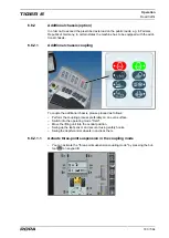
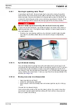
Red LED (
1
) lights on the R-Touch when the engine brake is active.
1
Summary of Contents for Tiger 6
Page 3: ...Contents 3 564 Contents...
Page 4: ...Contents 4 564...
Page 13: ...Preface 13 564 1 Preface...
Page 14: ...Preface 14 564...
Page 22: ...Safety 22 564...
Page 23: ...Safety 23 564 2 Safety...
Page 24: ...Safety 24 564...
Page 41: ...General View and Specifications 41 564 3 General View and Specifications...
Page 42: ...General View and Specifications 42 564...
Page 53: ...General Description 53 564 4 General Description...
Page 54: ...General Description 54 564...
Page 57: ...Operating Components 57 564 5 Operating Components...
Page 58: ...Operating Components 58 564...
Page 98: ...Operation 98 564...
Page 99: ...Operation 99 564 6 Operation...
Page 100: ...Operation 100 564...
Page 226: ...Operation Defoliator 226 564 RIS defoliator RES defoliator...
Page 291: ...Operation Infeed conveyor 291 564 2 1 1 Infeed conveyor control block...
Page 299: ...Operation Strainer wheels turbines 299 564 4 Rpm strainer wheels...
Page 325: ...Operation Bunker unloading 325 564 6 19 Bunker unloading...
Page 361: ...Maintenance and Service 361 564 7 Maintenance and Service...
Page 362: ...Maintenance and Service 362 564...
Page 418: ...Maintenance and Service Defoliator 418 564 Defoliator in the maintenance position...
Page 475: ...Malfunction and Remedies 475 564 8 Malfunction and Remedies...
Page 476: ...Malfunction and Remedies 476 564...
Page 528: ...Lists Tables Plans Diagrams Maintenance Verification 528 564...
Page 558: ...558 564...
Page 559: ...Index 559 564 10 Index...
Page 560: ...Index 560 564...


