Intense, Oracle,
Reveal Illuminated Mirror
Installation & aftercare instructions
Please retain for future reference
(Oracle Shown for Illustrative Purposes)
Customer Services, Roper Rhodes Ltd, Brassmill Lane Trading Estate, Bath, BA1 3JF
|
Tel: 01225 303 900
|
Fax: 01225 448 877
|
Email: sales@roperrhodes.co.uk
|
Web: www.roperrhodes.co.uk
INSTALLATION PROCEDURE
The wall surface must be of suitable strength and construction.
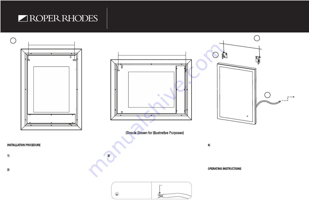
1) Measure the distance (x) between the wall fixing pins on the back of the
mirror. For horizontal mounting measure between the fixing pin and the keyhole
slot.
2) For portrait mounting, mark out the wall mounting plates on the wall using a
pencil to the desired height ensuring they are spaced at distance (x).
If mounting landscape mark out 1 wall mounting plate and mark out a single
screw position using dimension (x) for the keyhole slot.
Drill the marked out positions and fit the wall plugs accordingly. Secure the wall
mounting plates in position with the screws provided.
NOTE: The wall plugs supplied are only suitable for solid stone / brick walls. For
plasterboard walls use specialist wall plugs.
3) The next step is to make the electrical connection from the mirror to the
mains supply. Use the connection wire found at the rear of the mirror to make
the necessary connections in accordance with the current IEE regulations. A
second person will need to hold the mirror in place whilst electrical
connections are made.
4) The mirror should slide onto the wall mounting brackets and secure into
place. For a landscape installation, the keyhole slot should be positioned on a
single screw first before sliding onto the wall bracket for ease of installation.
To remove the mirror, the mirror should first be lifted and then pulled away from
the wall.
OPERATING INSTRUCTIONS
Lighting is turned on / off by waving a hand past the IR sensor on the mirror
glass, which is positioned in the bottom right when hung portrait and bottom left
when hung landscape. The heated pad is on when the light is on. DO NOT leave
on for prolonged periods of time.
Strip wires to a suitable
length. DO NOT connect
to a plug & socket outlet.
THIS PRODUCT IS MANUFACTURED TO CLASS I
CATEGORY AND MUST HAVE AN EARTH CONNECTION.
! IF IN DOUBT CONSULT YOUR ELECTRICIAN !
Colour Coding:
L - Live
= Brown
N - Neutral = Blue
- Earth
= Green & Yellow
1
Measure
Distance X
Measure
Distance X
2
3
4
Mains Supply
Distance X
Back View
Portrait View
Landscape View


