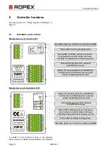
Controller functions
RES-403
Page 21
This indicator moreover permits disturbances in the
control loop (loose connections, contacting or wiring
problems) as well as any line disturbances to be
observed extremely effectively and interpreted accor-
dingly. The same applies if mutual interference occurs
between several neighboring control loops.
This output is not potential-free and might
have the potential of the secondary voltage
of the impulse transformer.
External grounding is not allowed. If this war-
ning is ignored, the controller will be
damaged by frame currents.
For the terminals of the external temperature
meter touch voltage protection must be
installed.
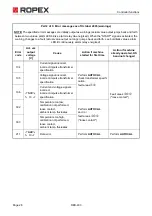
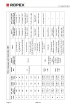
If an alarm is signaled, the analog output at terminals
14+15 is used to display a selective error message
(
ª
section 6.12 "Error messages" on page 26).
6.4
Automatic zero calibration
(AUTOCAL)
Because of the automatic zero calibration (AUTOCAL)
function, there is no need to adjust the zero point manu-
ally on the controller. This function matches the con-
troller to the current and voltage signals that are pre-
sent in the system. The zero point is calibrated in the
factory to the initial temperature (ambient temperature,
20°C).
You should always wait for the heatsealing
band and the bar to cool down (to ambient
temperature) before activating the AUTOCAL func-
tion.
Variable initial temperature:
On controllers manufactured as of April 2005, the initial
temperature for the "AUTOCAL" function can be set in
the 0…+40°C range in the visualization software
(
ª
section 6.10 "Diagnostic interface/visualization soft-
ware (as of October 2005)" on page 25). This setting is
remembered if the controller is switched off and then on
again.
As of SW Revision 107, the "External calibration tem-
perature" setting can also be selected in the visualiza-
tion software. The initial temperature for this setting can
be specified in the +3…+40°C range via the set point
potentiometer (terminals 16+17;
ª
section 6.2 "Tem-
perature setting (set point selection)" on page 19). The
value selected at the set point potentiometer must be
present when the "AUTOCAL" function is activated.
If the specified value is too high (greater than 40°C) or
if the selected value varies, an error message appears
(error codes 115 and 116;
ª
section 6.12 "Error mes-
sages" on page 26).
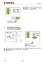
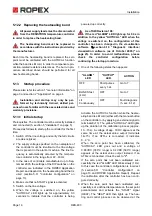
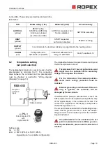
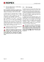
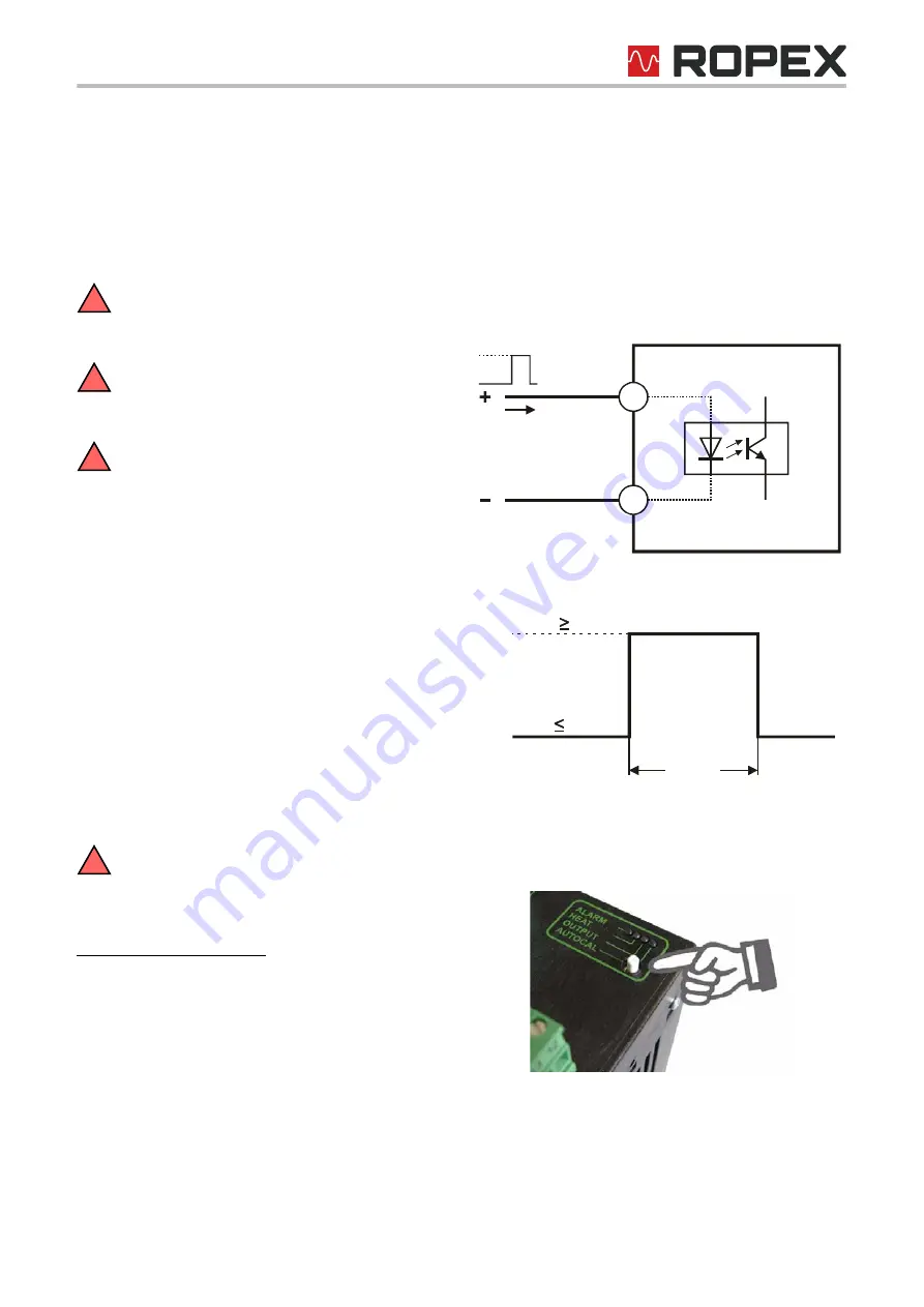
The AUTOCAL function is activated either by means of
a 24VDC pulse at terminals 8+13 or by pressing the
AUTOCAL button on the controller.
The automatic calibration process takes about
10…15 seconds. The heatsealing band is not heated
during this process.
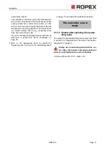
The yellow LED on the front panel lights up when the
AUTOCAL function is active. The actual value output
!
!
!
!
13
8
RES- 403
max. 6mA
GND
AUTOCAL
24VDC
0,1...5s
LOW: 2VDC
AUTOCAL
HIGH: 12VDC

