Commissioning and operation
Page 24
RES-5008
Version 2
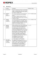
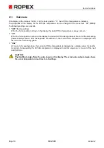
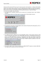
After each change of the heating element, the zeroing must be performed in case of cold elements and cold envi-
ronment (i.e. silicone, PTFE-cover, sealing bar, among others) with the function AUTOCAL, in order to compen-
sate production-related tolerances of the heating element resistances.
When changing the heating element, we recommend that the base is checked, for example silicone profile with
PTFE-fabric band. A damaged base must be replaced to ensure that the heating element functions correctly.
If a new heating element is used, the above-described procedure for burning in must be performed.
If the new heating element has a different specification, it must be ensured that the voltage applied is adjusted to
the resistance of the heating element. If the new heating element has another specification (e.g., heating element
cross section, alloy), the application must be checked (
ROPEX-application report). If this specification was not
taken into account in the application report, the application report must be updated in accordance with the new
requirements.
8.4
Commissioning rules
Observe here section 3 "Safety" on page 4 and section 5.1 "Use" on page 10.
8.4.1
Initial commissioning
Requirement: Device is correctly mounted and connected (
section 6 "Transport and Storage" on page 12).
Proceed as follows when commissioning the regulator RESISTRON
®
Temperature Controller RES-5008 for the
first time:
1. Switch off mains voltage and 24 VDC power supply; verify lack of voltage.
2. Make sure that there is no 24 V-START signal present.
3. Switch on the mains voltage and 24 VDC power supply in any order.
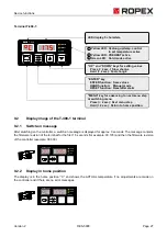
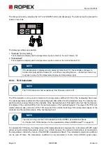
4. After the voltage is switched on, the yellow “AUTOCAL” LED lights up for about 0.3 seconds and displays
the correct switch-on process of the regulator. As long as no mains voltage is present, this LED blinks slowly
(1 Hz).
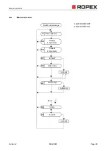
5. The following statuses can then result:
WARNING
The assembly, installation and commissioning may be performed only by technically trained
and competent persons. The persons must be familiar with the dangers associated with it and
guarantee provisions.
NOTE
In addition to the yellow LED “AUTOCAL”, if the red LED “ALARM” lights up for 0.3 seconds,
after switching on, the configuration with the visualisation software has been changed for
this regulator (
section 9.22 "USB-interface for visualisation software ROPEXvisual
page 45). The regulator’s configuration must be checked to avoid malfunctions before contin-
uing with commissioning.
“ALARM” LED
“OUTPUT” LED
MEASURE
OFF
Short pulses every 1.2 seconds
Continue with item 6
BLINKS quickly (4 Hz)
OFF
Continue with item 6
Permanently ON
OFF
Error diagnosis (
Chapter 9.25)


