Side 4
3.
Connection of Smartbox
3.1
Descriptions
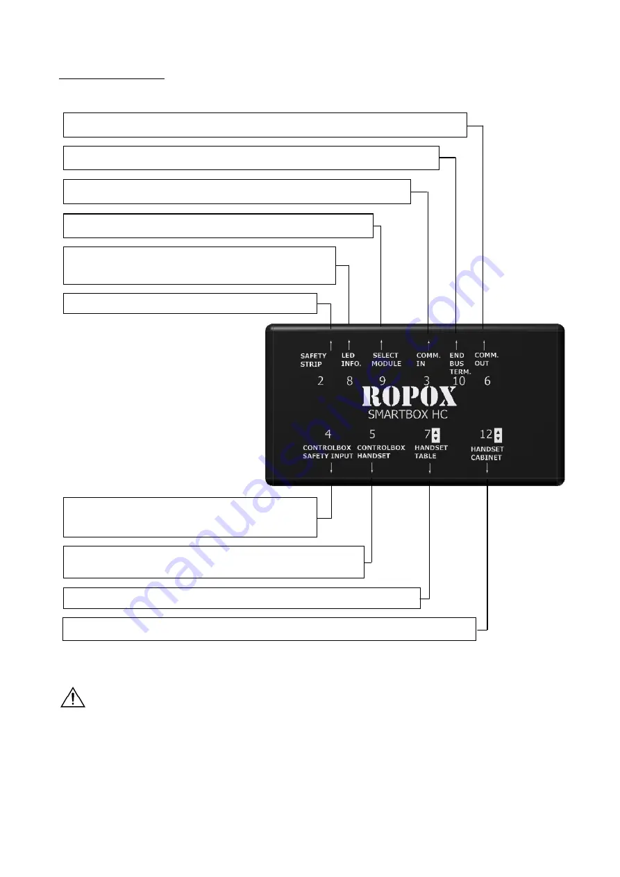
Pos. 3 is not being used on the first Smartbox in the system.
Pos. 6 is not being used on the last Smartbox in the system.
4. Connection to Controlbox, modular plug
(Controlbox pinch input)
5. Connection to controlbox, Din plug (To controlbox handset)
7. Connection of the control switch for the table
2. Connection of Safety strip
8. Led, light (to be used at power up and trouble
shooting)
9. Dip switch for Smartbox settings (naming the Smartbox)
3. Communication input from previous Smartbox (Comm. In)
10. Dip switch (indicates first and last Smartbox connected)
6.
Connection to next Smartbox (Comm. Out)
12. Connection of the control switch for the VertiElectric (optional)


