background image

REMOTE OCEAN SYSTEMS 

SEASTAR OPERATION AND MAINTENANCE MANUAL


10-01313   REV D 

29 

3.


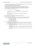
Inspect the outside of the light for signs of a short, such as browned, blackened or melted components. 
Disconnect the power connector and inspect for signs of a short. 

4.


Verify the power cable is securely connected to the light. 

5.


Verify the power is turned on and any dimmers are set high enough to allow light output. 

6.


Verify the DC analog dimming signal or serial dimming is set high enough to allow light output. 

7.


Verify the power supply is outputting the expected voltage: 110 to 130VAC or 20 to 26 VDC. 

8.


Inspect the light for signs of water intrusion. 


WARNING 

Disconnect the Seastar from power prior to servicing or troubleshooting internal 
components.  

Seastar contains high voltages and currents, and should be serviced only by 
trained technicians. 

9.


If the problem has not been identified and resolved, open the light (5.2.1)

10.


Check for loose or disconnected wires. 

11.


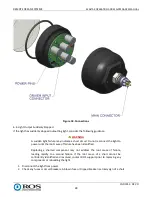
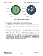
Disconnect the driver input connector from driver board, check the connector for signs of a short. 

a.


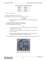
Use volt meter to check for resistance on the driver board input pins (see Figure 19)

i.


Pin 1 to pin 2: open circuit 

ii.


Pin 2 to pin 3: open circuit 

iii.


Pin 3 to pin 4: open circuit 

iv.


Pin 4 to pin 5: open circuit 

12.


Check for broken components or signs of a short.  

a.


 Use volt meter to check fuse (F1) for continuity.  If resistance is greater than 3 ohms, the fuse 
has been tripped and there may be a short circuit somewhere in the driver board or LED array.   

b.


Use volt meter to check for isolation 

i.


Check resistance between Output 1 pin and PCB mounting screw, resistance should read 
open circuit. 

ii.


Check resistance between Output 2 pin and PCB mounting screw, resistance should read 
open circuit. 

iii.


Check resistance between Output 3 pin and PCB mounting screw, resistance should read 
open circuit. 


Summary of Contents for SEASTAR

Page 1: ...rmation disclosed herein This document is furnished in confidence on the express understanding that neither it nor any reproduction thereof will be disclosed to others or used for the purpose of manuf...

Page 2: ...4 4 4 3 DC Inrush Current 17 4 5 Temperature Protection 18 4 5 1 120VAC 18 4 5 2 24VDC 18 4 6 Electrical Protection 18 4 6 1 24VDC 18 5 Maintenance 19 5 1 Scheduled Maintenance 19 5 2 Unscheduled Main...

Page 3: ...12 Closing the Seastar 21 Figure 13 Window Reflector and LED Array Replacement 22 Figure 14 Top Layer 120VAC Driver Board 24 Figure 15 U4 on Top Layer 24VDC Driver Board 25 Figure 16 Q1 on Bottom Laye...

Page 4: ...ct or penal damages d The laws of the State of California shall govern this warranty In the event the defect is determined to be within the terms of this warranty then ROS agrees to repair and or repl...

Page 5: ...ts and are able to provide assistance during installation and or operation of these products If you have any questions or problems with this product that are not covered by this manual or instruction...

Page 6: ...OTE OCEAN SYSTEMS SEASTAR OPERATION AND MAINTENANCE MANUAL 10 01313 REV D 6 Change Record REV DESCRIPTION DATE A SEE EC 03199 08JUN20 B SEE EC 03210 18JUN20 C SEE EC 03228 20AUG20 D SEE EC 03358 03MAY...

Page 7: ...light for deep ocean use Options include flood or spot reflectors and 120 VAC or 24 VDC power AC powered lights provide full range flicker free phase cut dimming DC lights provide dimming via 0 10 V...

Page 8: ...m patterns Table 1 Mechanical Specifications Spot Wide Weight in air 1 9 lb 86 kg 1 8 lb 81 kg Weight in water 1 0 lb 41 kg 91 lb 45 kg Depth rating 20 000 ft 6 km Operating temp 10 to 40 C Storage te...

Page 9: ...REMOTE OCEAN SYSTEMS SEASTAR OPERATION AND MAINTENANCE MANUAL 10 01313 REV D 9 Figure 2 Beam Patterns...

Page 10: ...NCE ON THE EXPRESS UNDE RSTANDI NG THAT NEI THER I T NOR ANY REPRODUCTI ON THEREOF W I LLBE DI SCLOSED TO OTHERS OR USED FOR THE PURPOSE OF M ANUF ACTURE OR PROCUREM ENT APPROVED FOR I NTERNAL RELEASE...

Page 11: ...e of the rectified AC output from the LCU to achieve low light levels at the lower end of the dimming range Use LCU application to turn on the light the corresponding slider will determine the light o...

Page 12: ...NUAL 10 01313 REV D 12 Figure 5 AC Lux Output with Triac Dimming 4 3 2 AC Crydom Dimming Figure 6 shows the Seastar light output when used with a Crydom dimmer The test was performed using a 10PCV2415...

Page 13: ...number of the Seastar unit and see below for proper operation 10 01341 01 This version is a 24VDC low power light controlled by a 0 5VDC voltage supply with max power of 21W 10 01317 01 This version...

Page 14: ...with RS485 control The serial dimming Seastar can be operated using the ROS Eos GUI or by sending serial commands from a customer device or software Table 3 lists ROS VISCA serial parameters Table 4...

Page 15: ...Data bits 8 Start bits 1 Stop bits 1 Parity None Flow control None Table 4 Serial Commands and Inquiries Command Packet Note Set Address 88 30 0x ff x address 1 7 Returns 88 30 0y y x 1 When setting t...

Page 16: ...text z0 50 unit pn unit rev unit sn cca pn cca rev cca sn firmware pn firmware rev z address 8 byte Get Temperature 8x 09 10 03 ff x address Returns z0 10 10 03 0y 0y 0y ff z address 8 byte yyy Hexade...

Page 17: ...8 Returned when the command format is different or when a command with illegal command parameters is accepted Command Not Executable z0 6y 41 ff z address 8 y socket default 1 Returned when a command...

Page 18: ...0 Celsius Once the light driver has gone below 50 Celsius it will automatically return to its original light output level 4 6 Electrical Protection 4 6 1 24VDC The DC light driver will stop the light...

Page 19: ...he Seastar has been disassembled as this may lead to leaks in service These components are available as part of a rebuild kit 1 Shut off the power to the Seastar and disconnect the power cable 2 Use a...

Page 20: ...ring from the housing 2 Clean the end bell and bezel threads to remove as much fouling and dried thread locking compound appears as red plastic as possible 3 Test thread the end bell and bezel togeth...

Page 21: ...g should be visibly compressed and the window should be tightly held 13 Mark the housing and the bezel as shown in Figure 12 NOTE Tightening the bezel requires approximately 40 ft lb of torque e g 40...

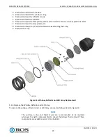
Page 22: ...7 Remove and save the array power pins 8 Remove and save the 5 Philips flat head screws attaching the array 9 Remove the array Figure 13 Window Reflector and LED Array Replacement 5 2 4 Replace the W...

Page 23: ...servicing or troubleshooting internal components NOTE The replacement connector comes in a kit from Remote Ocean Systems which should include any materials and special hardware required to replace th...

Page 24: ...ponents 1 Remove the end bell and disconnect the wiring 5 2 1 2 Remove the circuit card from the housing and discard it 3 Place the thermal pad onto the housing NOTE Use care to align the array power...

Page 25: ...ERATION AND MAINTENANCE MANUAL 10 01313 REV D 25 Figure 15 U4 on Top Layer 24VDC Driver Board Figure 16 Q1 on Bottom Layer 24VDC Driver Board 5 Insert and tighten the two mounting screws shown in Figu...

Page 26: ...REMOTE OCEAN SYSTEMS SEASTAR OPERATION AND MAINTENANCE MANUAL 10 01313 REV D 26 Figure 17 AC Driver Circuit Card Replacement...

Page 27: ...r or bezel backing out under pressure cycling or vibration due to missing thread locking compound Housing and o ring not lubricated correctly 6 2 Light Output Gradually Decreased If the light output h...

Page 28: ...o not reconnect the light to power until the root cause of failure has been identified Replacing a shorted component may not address the root cause of failure leading rapidly to a second failure If th...

Page 29: ...technicians 9 If the problem has not been identified and resolved open the light 5 2 1 10 Check for loose or disconnected wires 11 Disconnect the driver input connector from driver board check the con...

Page 30: ...the light is detected attempt to dim the light with the GUI If the light works with the GUI the light detected an overvoltage MOSFET overcurrent or LED overcurrent condition Problem with customer dimm...

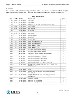
Page 31: ...10 01285 01 INSULATOR 90 AC 10 01293 01 PWA LED ARRAY 120 VAC X 90 DC 10 01293 02 PWA LED ARRAY 24 VDC X 100 AC 10 01279 01 PWA DRIVER 120VAC X 100 DC 10 01290 01 PWA DRIVER 24V DC X 110 60 20037 4 O...

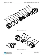
Page 32: ...EMS SEASTAR OPERATION AND MAINTENANCE MANUAL 10 01313 REV D 32 30 40 120 170 2X 50 80 70 180 5X 210 3X 90 60 10 Figure 20 Front Explode View 160 4X 110 20 220 100 140 2X 190 140 REF 160 REF Figure 21...

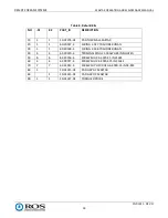
Page 33: ...RING 2 037 70 SHORE BUNA N 30 1 1 60 20148 4 O RING 2 148 70 SHORE BUNA N 40 4 4 62 20320 4 TERMINAL RING 22 18AWG 4 INSULATED 50 6 6 62 20156 4 SCREW SHHX 4 40X0 25 IN 316SS 60 4 4 62 00077 4 SCREW...

Reviews: