REMOTE OCEAN SYSTEMS
SEASTAR OPERATION AND MAINTENANCE MANUAL
10-01313 REV D
3
Figures
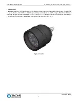
Figure 1. Seastar .........................................................................................................................................................7
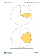
Figure 2. Beam Patterns .............................................................................................................................................9
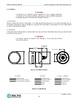
Figure 3. Installation Outline ................................................................................................................................... 10
Figure 4. Sample Wiring .......................................................................................................................................... 10
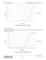
Figure 5. AC Lux Output with Triac Dimming .......................................................................................................... 12
Figure 6. AC Lux Output with Crydom Dimming...................................................................................................... 12
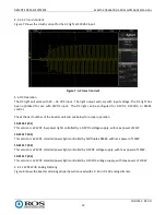
Figure 7. AC Inrush Current ..................................................................................................................................... 13
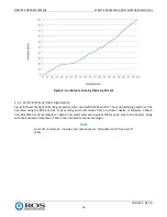
Figure 8. Lux Output vs Analog Dimming Percent ................................................................................................... 14
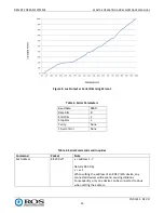
Figure 9. Lux Output vs Serial Dimming Percent ..................................................................................................... 15
Figure 10. DC Inrush Current ................................................................................................................................... 17
Figure 11. Driver Circuit Card Connections ............................................................................................................. 20
Figure 12. Closing the Seastar ................................................................................................................................. 21
Figure 13. Window, Reflector and LED Array Replacement .................................................................................... 22
Figure 14. Top Layer 120VAC Driver Board ............................................................................................................. 24
Figure 15. U4 on Top Layer 24VDC Driver Board .................................................................................................... 25
Figure 16. Q1 on Bottom Layer 24VDC Driver Board .............................................................................................. 25
Figure 17. AC Driver Circuit Card Replacement ....................................................................................................... 26
Figure 18. Connections ............................................................................................................................................ 28
Figure 19. Driver Input and Output Power Pins ...................................................................................................... 30
Figure 20. Front Explode View ................................................................................................................................. 32
Figure 21. Back Explode View .................................................................................................................................. 32
Tables
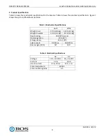
Table 1. Mechanical Specifications.............................................................................................................................8
Table 2. Electrical Specifications ................................................................................................................................8
Table 3. Serial Parameters ....................................................................................................................................... 15
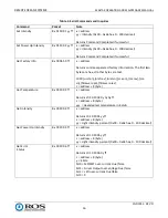
Table 4. Serial Commands and Inquiries ................................................................................................................. 15
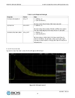
Table 5. Serial Response Messages ......................................................................................................................... 17
Table 6. Threads Size vs. Recommended Torque .................................................................................................... 24
Table 7. Bill of Materials .......................................................................................................................................... 31
Table 8. Rebuild Kits ................................................................................................................................................ 33

