

REMOTE OCEAN SYSTEMS
SEASTAR OPERATION AND MAINTENANCE MANUAL
10-01313 REV D
17
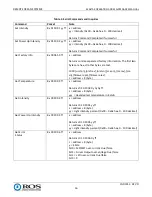
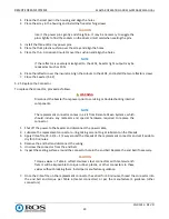
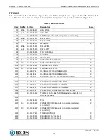
Table 5. Serial Response Messages
Response
Packet
Note
Command Completed
z0 5y ff
z = a 8
y = socket (default 1)
Returned when the command has been executed
Syntax Error
z0 60 02 ff
z = a 8
Returned when the command format is different or when a
command with illegal command parameters is accepted.
Command Not Executable
z0 6y 41 ff
z = a 8
y = socket (default 1)
Returned when a command cannot be executed due to
current conditions. For example, when user issues a light
intensity command with a value greater than the maximum
allowed value.
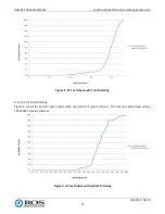
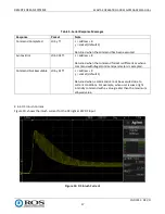
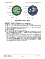
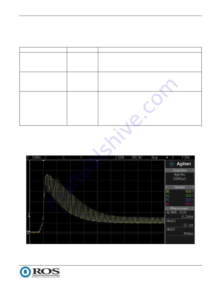
4.4.3.
DC Inrush Current
Figure 10. shows the inrush current for the DC light at 24VDC input.
Figure 10. DC Inrush Current