REMOTE OCEAN SYSTEMS
SEASTAR OPERATION AND MAINTENANCE MANUAL
10-01313 REV D
24
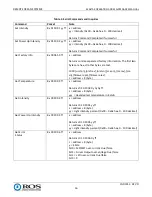
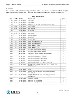
Table 6. Threads Size vs. Recommended Torque
Thread
Torque
7/16-20
35 ft lb
1/2
–
20
54 ft lb
9/16
–
18
76 ft lb
5/8
–
18
106 ft lb
8.
Close the Seastar (5.2.2)
5.2.6.
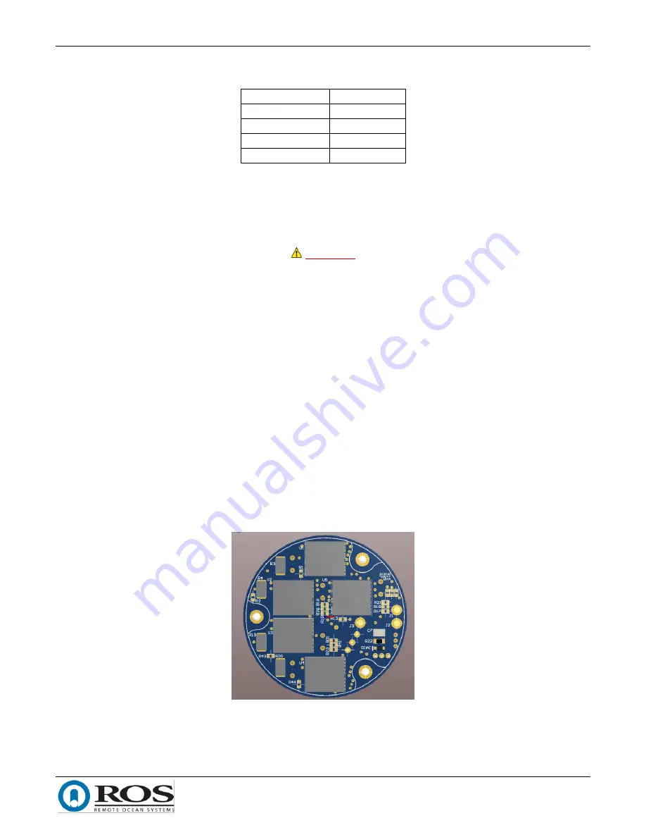
Remove and Replace the Driver Circuit Card
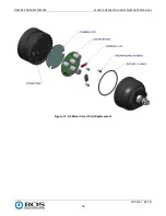
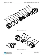
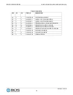
To replace the driver circuit card, proceed as follows. Refer to Figure 17.
WARNING
Disconnect the Seastar from power prior to servicing or troubleshooting internal
components.
1.
Remove the end bell and disconnect the wiring (5.2.1).
2.
Remove the circuit card from the housing and discard it.
3.
Place the thermal pad onto the housing.
NOTE
Use care to align the array power pins with the driver sockets when inserting
the replacement driver circuit card.
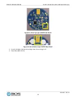
The 120VAC driver requires heat pad to be placed between the housing and U1,
U2, U3, U4, and U5.
24VDC driver requires heat pad to be placed between U4 and housing and a TO-
220 heat pad to be placed between Q1 and Q1 PCB footprint.
4.
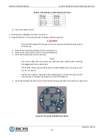
Place the replacement driver circuit card into the housing and seat it onto the array power pins.
Figure 14. Top Layer 120VAC Driver Board

