CHAPTER 5 – MANTINTENANCE –REPAIRS
12
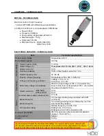
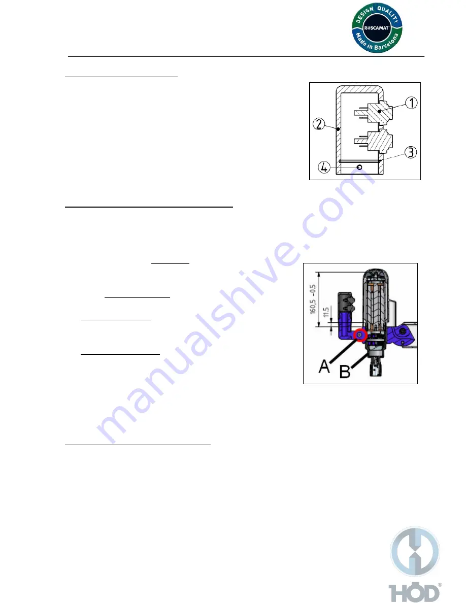
MOTOR GRIP REPLACEMENT
Ref.MO102404
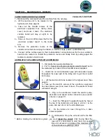
1. - Disconnect the main switch and the machine form the net plug.
2. - Remove the push buttons (1) and disconnect from its FASTON
plug.
3.- Take out the Allen screw (4) that fix the motor trigger to the
motor head and remove the motor trigger (2) by pulling it out.
*For reassembling, please, proceed the other way round. Do not
force the wires when placing the case
MOTOR AND COOLING FAN REPLACEMENT
MotorTS-XII: Ref.(See page 15)
Cooling fan: Ref.AF211003
1. - Disconnect the main switch and the machine form the net plug.
2. - Dislodge the motor housing by unscrewing the 2 ALLEN screws that fix it at the motor head.
3.1. - To replace the cooling fan of the upper part of the motor,
move out and dislodge it and insert the new cooling fan
by pressure.
3.2. - to replace the motor:
3.2.1. - Unplug the FASTON connection of the motor.
*Single speed motor:
3.2.2. – Unscrew the Allen screw (A) of the frontal part of the
head and extract the motor moving it upwards.
*
Double speed motor:
3.2.2.- Dislodge the motor slide collar (B)-first pull out the
“seeger ring” of the slider bottom part- and untight the ALLEN
screw from the frontal part of the headmember . Extract the
motor by moving it upwards.
*Proceed the other way round for its assembling ensuring that the motor position keeps the right
measures towards the headmember like showed on the picture attached.
LUBRICATION PUMP REPLACEMENT
Ref.MO300603
(*For machines equipped with this option)
1. - Disconnect the main switch and the machine form the net plug.
2. - Separate the speed and lubrication regulating buttons.
3. - Remove the 4 ALLEN screws from the electric box casing located in the radial arm.
4.- Disconnect of the “lubrication control board” the speed and lubricating cables so that you will
be able to move our the electric box.
5.- Remove the 2 FASTON terminal and the oil inlet-outlet pipes of the pump.
5. - Take out the 2 ALLEN screws which fix the lubrication pump and replace for the new one.
*For reassembling, please repeat the process in the reverse order.
Summary of Contents for MOSQUITO
Page 20: ...20 ...
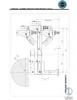
Page 23: ...CHAPTER 8 WORKING AREAS ROSCAMAT MOSQUITO vertical 23 ...
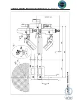
Page 24: ...CHAPTER 8 WORKING AREAS ROSCAMAT MOSQUITO V H Vert Horizontal 24 ...
Page 25: ...CHAPTER 8 MACHINE SECTION 25 ...
Page 27: ...CHAPTER 8 ELECTRICAL DIAGRAM CONNECTIONS 27 ...
Page 28: ...CHAPTER 8 ELECTRICAL DIAGRAM CONNECTIONS AUT LUBRICATION 28 ...
Page 29: ...CHAPTER 8 NOTES 29 DATE DESCRIPTION Date of creation September 2009 ...


