background image

CHAPTER 0 – INTRODUCTION                                                                              


3


Dear customer: 


We congratulate your election getting a “ROSCAMAT” tapping machine that encourages 
ourselves continuing our main job which consists on offering our customers a simple, 
reliable and flexible system to produce quality threads and associated operations. 
 
This Operation’s Manual is given to you with the aim to help setting up and operate the 
machine chosen by you. We suggest a careful reading of its contain, specially on pages 
where installation and maintenance are detailed.  
 
We also would like to take this opportunity  to thank for choosing ROSCAMAT and wish  
a long life for your machine so that may grant your great investment at your decision of   
purchasing a ROSCAMAT

®

.  


Summary of Contents for MOSQUITO

Page 1: ...2 08250 St Joan de Vilatorrada Barcelona Spain 938764359 938764242 938767738 938764044 E mail comercial tecnospiromt com http www tecnospiromt com roscamat roscamat com http www roscamat com Serial nr Machine nr Year of manufacture Motor Type Speed ...

Page 2: ... or and cooling fan substitution 12 Oil Pump replacement 12 Variator s board replacement 13 Tool Lubrication system kit instructions for mounting 13 Chapter 6 Replacement parts list 14 Chapter 7 Standard product range 16 Chapter 8 Annex 19 Technical data Technical motor characteristics Variator 20 Technical data Turning torque NM for threading Machine taps 21 Working areas ROSCAMAT MOSQUITO 22 Wor...

Page 3: ...y threads and associated operations This Operation s Manual is given to you with the aim to help setting up and operate the machine chosen by you We suggest a careful reading of its contain specially on pages where installation and maintenance are detailed We also would like to take this opportunity to thank for choosing ROSCAMAT and wish a long life for your machine so that may grant your great i...

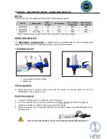
Page 4: ...radial arm The motor turning speed and the automatic tool lubrication optional control are adjustable by means of the buttons being located over the radial arm The speed can be thus adapted to every thread type The toolholders or tap holders with or without safety clutch are also apt to be fitted to the modules by means of a quick change system 1 Base 2 Lifter positioner 3 Lifter case Electronic b...

Page 5: ...which allows us to set the motor in 4 positions at 90º ant tap in horizontal sites Orientable head VH 1 Horizontal turn clamp handle 2 Milled nut Vertical operations Place the motor in vertical position and lock the handle 1 and the milled nut 2 The ROSCAMAT now is ready to work Horizontal operations Loose the milled nut 2 to unlock the joint of the motor Turn the head 90º till you reach the inter...

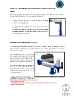
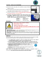
Page 6: ...r part of the radial arm If you have not get it as standard on your first purchase you can buy by separate and assembly whenever you care for The lubrication time is counted in seconds and adjusted by means of the button potentiometer located on the casing of the radial arm The tank oil filler plug is located on top casing of the radial arm After filling up the oil reservoir because of being empty...

Page 7: ...alter the machine structure or motor component Any additional work at the machine installation or improper handling may suppose the immediate lost of its warranty 3 Be careful with the dress accessories and others such as long hair gloves and jewellery 4 Always use eye protective glasses when operating the machine 5 Don t insert your fingers into the vicinity of the head stop when the arm is neari...

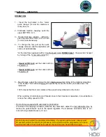
Page 8: ... according to the material properties to be thread The mentioned speed is adjusted by means the button 5 located over the radial arm 100 means that the motor rotates at the speed being indicated on the motor When working in hard steels and threads close to their maximum capacities it is advisable to reduce the cutting speed to 80 For machines equipped with automatic tap lubrication Provided of the...

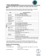
Page 9: ...t External alarm input OH2 External thermal relay tripped Motor protection OH4 Motor protection PTC thermistor OL1 motor overload thermoelectric protector motor relay Overload protection OLU Inverter unit overload Er1 Memory error Er2 Remote keypad communications error Er3 CPU error Operation protection Er6 Operation procedure error Er8 RS485 comunication error ErF Date save error due to undervolt...

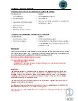
Page 10: ...times in succession in a state of the highest setting position of the lubrication regulating control Main features of the cutting oil type to be used Use pure cutting oil without additives Viscosity 20 40 cSt Additives E P extreme pressure Sulphur Phosphorous and Chlorine inactives It does not contain solvents WARRANTY The warranty period for the machine is 12 months The warranty does not cover an...

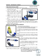
Page 11: ...d 1 located below the headmember that fixes the stay spindle b Remove the screws 3 that hold the headmember to the arm 4 Take out the spindle of the arm damper and then unscrew the damper regulating screw C page 7 5 Drop the arm to move the damper out 6 Attach the new damper and screw in the regulating screw again Bear in mind that the screw spindle must fit the end of the damper Now place the spi...

Page 12: ...crew A of the frontal part of the head and extract the motor moving it upwards Double speed motor 3 2 2 Dislodge the motor slide collar B first pull out the seeger ring of the slider bottom part and untight the ALLEN screw from the frontal part of the headmember Extract the motor by moving it upwards Proceed the other way round for its assembling ensuring that the motor position keeps the right me...

Page 13: ...e reservoir oil pump lubrication electric board set to the radial arm by means of the 2 ALLEN screws supplied 3 Install the oil and articulated pipe with lubrication nipple throughout the lower part of the tilting arm to get the oil outlet for the tap 4 Lift the machine till to be located in the highest point See page 6 5 Take out the ALLEN screws of the electronic equipment box case base cover an...

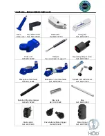
Page 14: ...amper See description in page 11 Regulating damper screw Ref MO100803 Mosquito vertical head Ref MO103604 Mosquito V H vertical head Ref MO200304 Spindle arm with screws Ref MO101204 Spindle of the arm damper Ref MO102303 Stay axis Ref CL010246 Stay Ref MO103204 Main switch Ref EL010396 Push buttons Motor trigger Ref EL010406 Motor trigger Ref MO102404 ...

Page 15: ...XI 2 speeds Ref AF220101 Motor TS XII 300 rpm Ref AF220301 Motor TS XII 600 rpm Ref AF220201 Lubrication board Ref MO300703 Lubrication pump Ref MO300603 Lubrication equipment cover Ref MO300207 Articulated pipe Ref MO300504 Tank oil filler Ref AC040526 Oil tank Ref MO3003A4 Quick change Ø19 mm Ref ACO90036 Table wheel 500x500 Ref AC080346 Table wheels 700x700 850x850 mm With brake Ref AC080386 Wi...

Page 16: ... safety clutch so that it slips when it reaches the hole bottom Tapholder without safety clutch for holding different tools with cylindrical shank and driving cube Type 1 Ø19 mm capacity M2 M16 QUICK CHANGE EXTENSION To separate 80 mm the tool from the head member and gain to difficult areas Ø coupling Ø19 mm REDUCER CUP To convert the output diameter from Ø19 to Ø13 and to get the possibility to ...

Page 17: ... DIN 371 M6 19 6 x 4 9 DIN 6 7 5 5 DIN 376 M8 19 8 x 6 2 DIN 376 M10 19 10 x 8 DIN 376 M12 1 9 x 7 DIN 376 M14 19 11 x 9 DIN 376 M16 19 12 x 9 DIN 376 THREADING DIE HOLDER For guided die threading Types Short Long different lengths Threading length Ø Coupl Short Long M5 M6 19 1 25 mm 100 mm M8 19 1 28 mm 100 mm M10 19 1 30 mm 120 mm M12 M14 19 1 33 mm 150 mm ...

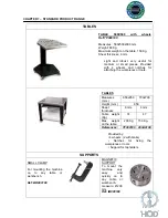
Page 18: ...rkpieces or tools TABLES Provided by 4 wheels 2 with brake Notches for fixing the workpieces or tools Support for tapholders Measures mm 850x850 700x700 Height mm 850 Sheet thickness 6 mm 4 mm Table weight Kg 74 47 Max weight on the table 200 Kg 150 Kg References TF000100 203A0100 SUPPORTS SMALL CLAMP For mounting the machine on to any table or workbench Ref BR000100 MAGNETIC SUPPORT To mount the ...

Page 19: ...l direction It consists on a compensated gas spring according to the machine weight Pneumatic 550 mm Stroke in vertical direction It consists of a collapsible column and torsion vertical cylinder Mechanic Ref EA000200 Pneumatic Ref EA0001A0 COLUMN For fixing the machine on the floor by means of 4 metallic dowels Measures Base 350x350x750 height Weight 20 Kg Ref CL000100 Attention the lifter can be...

Page 20: ...20 ...

Page 21: ...requency variations Voltage 10 to 10 Frequency 5 to 5 Momentary voltage clip capability When the input voltage is 165 V the inverter may keep running Even it drops below 165 V the inverter may keep running for 15 ms Rated current A With DCR 3 5 A Without DCR 5 4 A Required power supply capacity kVA 0 7 kVA Brakes Brake torque 100 average braking torque obtained with AVR control off Brake torque 15...

Page 22: ...el 100 130 Kg Steel 80 100 Kg Steel 80Kg Foundry GG22 Aluminium 100 HB 4 2 1 3 1 2 0 8 0 5 5 3 2 2 1 3 1 8 6 5 4 4 2 4 1 6 8 11 8 8 5 3 4 10 20 15 14 9 6 12 33 24 23 14 10 14 50 36 35 22 15 16 57 42 40 26 18 MACHINE TAPS Blind hole Helical flute tap Lubrication Through hole Straight flute tap with helical feed in Steel 80 Kg Rake angle 8 10 Cutting oil with additives Steel 80 Kg Rake angle 12 14 C...

Page 23: ...CHAPTER 8 WORKING AREAS ROSCAMAT MOSQUITO vertical 23 ...

Page 24: ...CHAPTER 8 WORKING AREAS ROSCAMAT MOSQUITO V H Vert Horizontal 24 ...

Page 25: ...CHAPTER 8 MACHINE SECTION 25 ...

Page 26: ...01803 Radial arm cover Bottom cros unit 42 CO011056 Bearing DIN618 HK0810 8x12x10 43 CO011076 Bearing DIN618 HK2016 20x26x16 46 CO011286 Bearing DIN618 HK2520 25x32x20 47 MO100104 Base 48 MO103304 Cross Unit 49 MO1004A3 Motor Head 50 MO103104 Radial Arm 54 CL021046 Spindle axis DIN7979 Ø8x36 56 MO102903 Lifter positioner 65 CA011766 Screw fixing motor to head DIN7984 M8x35 67 CL040586 Magnet base ...

Page 27: ...CHAPTER 8 ELECTRICAL DIAGRAM CONNECTIONS 27 ...

Page 28: ...CHAPTER 8 ELECTRICAL DIAGRAM CONNECTIONS AUT LUBRICATION 28 ...

Page 29: ...CHAPTER 8 NOTES 29 DATE DESCRIPTION Date of creation September 2009 ...

Page 30: ... Type Model range MOSQUITO Serial nr Machine nr Year of built as per description in the enclosed documents is in conformance with the Machine Directions 2006 42 CE and with the electromagnetic compatibility direction 2004 108 CE It conforms with the standards UNE EN ISO 12100 1 2004 UNE EN ISO 12100 2 2004 EN 60204 1 Name RAMON Surname JOU PARROT Post MANAGER Place and date ST JOAN DE VILATORRADA ...

Reviews: