CHAPTER 4 – TROUBLE SHOOTING
9
PROBLEM: THE MACHINE FAILS TO OPERATE, THE MOTOR DOES NOT START OR
STOPS
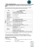
Remove the electronics box housing (2, page 4) thereby exposing the electronics, and check the
trouble condition by means of the showed display at the “variator’s board (inverter)”.
Items Detail
Specifications
Indication
Alarm mode
Reasons of lecture
Overcurrent
protection
OC 1: Overcurrent during acceleration
OC 2: Overcurrent during deceleration
OC 3: Overcurrent during running constant speed
Input phase loss
connection
L in: Input phase loss
Undervoltage
protection
LU: Undervoltage
Protección contra
Output phase loss
connection
OPL: Output phase loss.
Overvoltage
protection
OU1: Overvoltage during acceleration
OU2: Overvoltage during deceleration
OU3: Ovevoltage during running at constant speed
Overheat protection
OH1: Overheating during the heat sink
dbH: overheating of the DB circuit
External alarm
input
OH2: External thermal relay tripped
Motor protection
OH4: Motor protection (PTC thermistor)
OL1: motor overload; thermoelectric protector motor relay
Overload protection OLU: Inverter unit overload
Er1: Memory error
Er2: Remote keypad communications error
Er3: CPU error
Operation
protection
Er6: Operation procedure error
Er8: RS485 comunication error
ErF: Date save error due to undervoltage
Running or alarm mode
Alarm history saves and displays the last 4 trip codes and their detailed
description. Even with main power off, the alarm history data of the last
4 trips are retained.
.
- In any trouble shooting case, you must “reset” the machine and re-start the system again.
Switch off and on the machine. If the problem is due to the external voltage or current, you must
wait until it stabilizes. If the problem continues, get in touch with your distributor or manufacturer
.
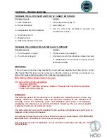
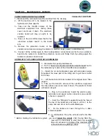
PROBLEM: THE TILTING ARM DROPS
Probable reason
Solution
1.- Not-equilibrated arm = Balance the arm according to the weight to be held. Verify
point C (page.7)
2.- Defective damper
= Replace it for a new one (page.11)
Summary of Contents for MOSQUITO
Page 20: ...20 ...
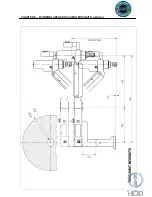
Page 23: ...CHAPTER 8 WORKING AREAS ROSCAMAT MOSQUITO vertical 23 ...
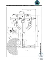
Page 24: ...CHAPTER 8 WORKING AREAS ROSCAMAT MOSQUITO V H Vert Horizontal 24 ...
Page 25: ...CHAPTER 8 MACHINE SECTION 25 ...
Page 27: ...CHAPTER 8 ELECTRICAL DIAGRAM CONNECTIONS 27 ...
Page 28: ...CHAPTER 8 ELECTRICAL DIAGRAM CONNECTIONS AUT LUBRICATION 28 ...
Page 29: ...CHAPTER 8 NOTES 29 DATE DESCRIPTION Date of creation September 2009 ...


