4
Lastbereich /
Load range
Belastungsdaten /
Load data
Hub
GTV light
Stroke
GTV light
max. Profillänge
GTN II
max. profile length
GTN II
max. Profillänge GTN II
mit Zwischengelenk
max. profile length GTN II
with Intermediate joint
max. Profillänge
GTN II (vertikal)
max. profile length
GTN II (vertical)
L1
L1 + L2
L3
400
1400 mm
nur auf Anfrage!
only on request!
250 mm*
600
1250 mm
nur auf Anfrage!
only on request!
250 mm*
800
1100 mm
nur auf Anfrage!
only on request!
250 mm*
L1
L2
L3
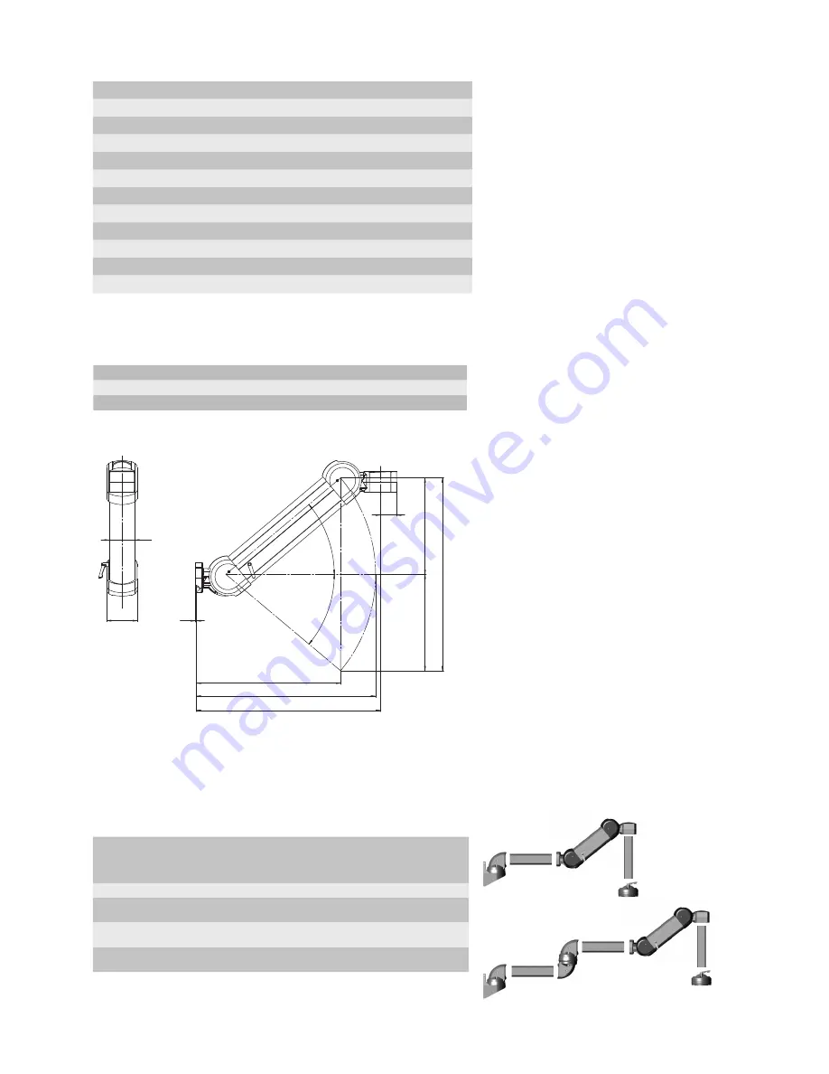
Abmessungen /
Dimensions
*Weitere Längen auf Anfrage /
Other length on request
A (Hub /
Stroke
in mm)
B (mm)
C (mm)
D (mm)
400
330
403
454
600
450
559
573
800
568
692
714
40
°
B
C
Hub/2
Hub/2
Hub = A
40
°
D
3
52
95
80
Hub = 400 mm /
Stroke = 400 mm
Bestell-Nr. /
Order No.
Lastbereich 1 (5 - 10 kg) /
Load range 1 (5 - 10 kg)
49.84 20 01
Lastbereich 2 (10 - 16 kg) /
Load range 2 (10 - 16 kg)
49.84 20 02
Lastbereich 3 (16 - 25 kg) /
Load range 3 (16 - 25 kg)
49.84 20 04
Hub = 600 mm /
Stroke = 600 mm
Lastbereich 1 (5 - 10 kg) /
Load range 1 (5 - 10 kg)
49.84 40 01
Lastbereich 2 (10 - 16 kg) /
Load range 2 (10 - 16 kg)
49.84 40 02
Lastbereich 3 (16 - 25 kg) /
Load range 3 (16 - 25 kg)
49.84 40 04
Hub = 800 mm /
Stroke = 800 mm
Lastbereich 1 (5 - 7 kg) /
Load range 1 (5 - 7 kg)
49.84 60 01
Lastbereich 2 (7 - 13 kg) /
Load range 2 (7 - 13 kg)
49.84 60 02
Lastbereich 3 (13 - 21 kg) /
Load range 3 (13 - 21 kg)
49.84 60 04
L1
Der Lastbereich errechnet sich aus:
- Gewicht der Steuerung / des Steuergehäuses mit
Einbauten
- evtl. verwendeter Kupplung / Neigungsadapter etc.
- vertikalem Profil bis zum Kopf des GTV light
The load range is calculated by:
- weight of the command unit / command enclosure
with installations
- possibly used coupling / inclination adapter, etc.
- vertical profile up to the head of the GTV light
L3


