background image

SERVICE AND MAINTENANCE 

RackView-Switch Manual 

18


Maintenance and Repair 

This Unit does not contain any internal user-serviceable parts.  In the event a Unit needs repair or maintenance, 

you must first obtain a Return Authorization (RA) number from Rose Electronics or an authorized repair center.  

This Return Authorization number must appear on the outside of the shipping container. 


See Limited Warranty for more information.   


When returning a Unit, it should be double-packed in the original container or equivalent, insured and shipped 

to: 


Rose Electronics 


Attn: RA __________ 


10707 Stancliff Road 


Houston, Texas 77099 USA   


Technical Support 

If you are experiencing problems, or need assistance installing your product, consult the appropriate section of 

this manual.  If, however, you require additional information or assistance, please contact the Rose Electronics 

Technical Support Department at: 


Phone: (281) 933-7673 


E-mail: TechSupport@rose.com  


Web:    www.rose.com  


Technical Support hours are from: 8:00 am to 6:00 pm CST (USA), Monday through Friday. 


Please report any malfunctions in the operation of this Unit or any discrepancies in this manual to the Rose 

Electronics Technical Support Department. 


Summary of Contents for RackView-Switch RV1-CSKVT17/DVI

Page 1: ...RackView Switch Sliding KVM Rack Drawer with Integrated KVM Switch Installation and Operation Manual 10707 Stancliff Road Houston Texas 77099 Phone 281 933 7673 techsupport rose com...

Page 2: ...mage in transit to prepay shipping charges to the warranty service location and to use the original shipping container or its equivalent You must call for a return authorization number first Under no...

Page 3: ...vironment This equipment generates uses and can radiate radio frequency energy and if not installed and used in accordance with the instruction manual may cause harmful interference to radio communica...

Page 4: ...15 Connecting the RackView Switch 15 Turning on the RackView Switch 16 Testing the RackView Switch 16 Configuring the Display Settings 16 Safety 17 Maintenance and Repair 18 Technical Support 18 Figur...

Page 5: ...24 Appendices Appendix A Specifications for RackView 17 and 19 Models 19 Appendix B Specifications for RackView 20 Model 20 Appendix C Part Numbers 21 Appendix D RackView Dimensions 22 Appendix E Rac...

Page 6: ...n TFT LCD monitor a tactile keyboard and a touchpad mouse The RackView Switch Drawer combines an optional 8 port digital DVI USB Audio KVM switch that is conveniently mounted in the rear of the RackVi...

Page 7: ...een audio and DC power A detailed list of contents can be found in the installation section of this manual Additional cables are usually ordered separately If the package contents are not correct cont...

Page 8: ...DELS RackView Switch Manual 3 RackView Switch Models The RackView Switch is available as described below RackView Switch Models RackView 17 and 19 Model RackView 20 Model Figure 1 RackView Switch Mode...

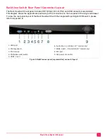
Page 9: ...ors on the rear panel of the single rail drawer To view the rear panel layout of the RackView Switch with the integrated 8 port digital KVM switch please refer to Appendix E 1 VGA port 6 Audio line in...

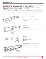
Page 10: ...d electrical equipment is powered off and that reliable grounding is provided for all rack mounted equipment When removing the RackView from the packing cartoon take care that the unit does not slide...

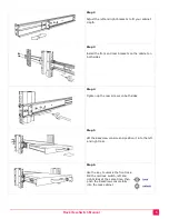
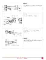
Page 11: ...ackets on the cabinet on both sides Step 4 Tighten up the rear screws on both sides Step 5 Lift the RackView console and position it into the left and right rails Step 6 Use the key to unlock the fron...

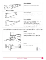
Page 12: ...rews in the rear of the RackView console on each side Step 9 Finish the installation as shown Should you need to use the set of long brackets for a cabinet depth of 32 60 39 37 inches 828 1000mm follo...

Page 13: ...s for both sides Tighten 3 screws to secure the bracket in place Note do not use only 1 screw as it may damage the RackView and the mounting rails Repeat the installation steps 1 9 above Should the ne...

Page 14: ...es the lock position Remove 4 Pull the rail release switch on each side Remove 5 Slowly pull the RackView console out from the mounting rails Remove 6 Push the rail lock switch back into position and...

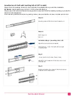
Page 15: ...rack mounted equipment When removing the RackView from the packing cartoon take care that the unit does not slide out of control Check 1 Mounting rails with front and rear brackets x 2 Check 2 Flat sc...

Page 16: ...e left and right mounting rails Step 5 Pull the mounting rail release switch on each side and push the RackView fully into the rack cabinet Step 6 Position of the rail release switch Step 7 Install 3...

Page 17: ...d bracket 19 84 32 60 inch 504 828mm 21 81 32 60 inch 554 828mm 26 22 37 87 inch 666 962mm Long bracket 32 60 39 37 inch 828 1000mm 32 60 39 37 inch 828 1000mm Mounting Screws 6 x Flat screws 6 x Roun...

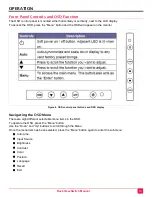
Page 18: ...l appear on the monitor Figure 4 OSD control panel buttons and OSD display Navigating the OSD Menu There are eight different selectable menu items in the OSD To operate the OSD press the Menu button U...

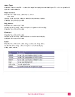
Page 19: ...input source of signal Press the menu button to enter Brightness Press the menu button to enter Use the Down and Up button to adjust the brightness of the display Press the menu button to enter Contra...

Page 20: ...Exit Press the exit button to quit the OSD menu Power Indicator GREEN ON RED STANDBY RED SUSPEND RED OFF Connecting the RackView Switch 1 Turn off your computer You should always turn off your compute...

Page 21: ...ds use the Windows Display Properties control panel to configure the display To open the Windows Display Properties click the right mouse button in a blank area of the Windows desktop and then select...

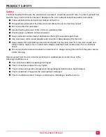
Page 22: ...power cords power adapter and connection cables designed for this Unit Keep objects that might damage this Unit and liquids that may spill clear from this Unit Liquids and foreign objects might come i...

Page 23: ...ainer or equivalent insured and shipped to Rose Electronics Attn RA __________ 10707 Stancliff Road Houston Texas 77099 USA Technical Support If you are experiencing problems or need assistance instal...

Page 24: ...t Ratio typical 1000 1 1000 1 Viewing Angle H V Left Right 170 Up Down 160 Left Right 170 Up Down 160 Pixel Pitch 0 264 x 0 264mm 0 098 x 0 294mm Response Time Rising 3 8ms Decay 1 2ms Rising 3 6ms De...

Page 25: ...7ms Decay 9ms Connectors and Controls Console Ports standard model one cable included 1 x DVI D 1 x HD15 VGA 1 x USB HID for USB keyboard and mouse 1 x USB2 0 for USB device connection from USB2 0 po...

Page 26: ...B Audio KVM Switch RV1 CSKVT17 KVM 8TDVI A1 1U 17 RackView Switch with an integrated 8 port DVI USB Audio KVM Switch RV1 CSKVT17 KVM 8TDVI A1 K6 1U 17 RackView Switch with an integrated 8 port DVI USB...

Page 27: ...ge size and weight varies with options such as KVM switch as below Package Size and Weight with Internal KVM Switch Model with KVM Switch Product Dimension D W H approx Packing Dimension D W H approx...

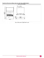
Page 28: ...RackView Switch Manual 23 RackView Dimensional Measurements with Internal KVM Switch RackView 20 Model Figure 6 Dimensions of RackView 20 model...

Page 29: ...a complete kit RackView KVM Switch the RackView and the Switch are connected internally All that is required is to connect the CPU cables DVI USB Audio from the rear panel of the switch to the host PC...

Page 30: ...an be ordered with optional DC power input for 12V 24V and 48VDC Select the DC voltage required then add the voltage to the RackView part number as nnDC For example adding 48VDC to a RackView 17 would...

Page 31: ...COM sales rose com 800 333 9343 Rose Electronics 10707 Stancliff Road Houston Texas 77099 Rose USA 281 933 7673 Rose Europe 49 0 2454 969442 Rose Asia 65 6324 2322 Rose Australia 61 0 421 247083 WWW...

Reviews: