4
UltraVista Installation and Operations Manual
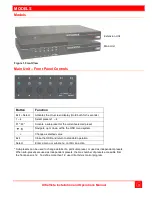
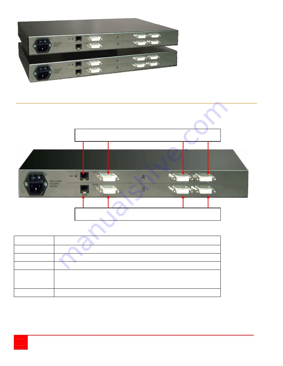
Extension Unit
Main Unit
Figure 2. Rear View
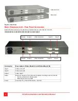
Main / Extension Unit – Rear Panel Connectors
Each UltraVista unit (main and extension) consists of two (2) video boards, A and B.
Video board “A” connects two video sources to a video output
Video board “B” connects two video sources to a video output
Connector
Description (Video Board A and Video Board B)
Input 1
Video source #1
Input 2
Video source #2
Output
Video output
Serial
External connection from equipment capable of sending serial commands
Run the UltraVista Control program
Externally execute the OSD
Power
Universal 110 – 240 VAC 50-60 Hz – 40 Watt
Serial Output (Video board A) Input 2 Input 1
Serial Output (Video board B) Input 2 Input 1


