background image

Rosen Aviation 

Document Number: 100318 


  Revision:                    A 
  Date: 03/11/08 

Template: 4.2.3-6-FM; Revision A; 16 May, 2005 

Page 7 of 13  


To configure the remaining output channels (2-8), copy the appropriate switch settings from  
Tables 1-3. Fixed modes will use either an ON/OFF, OFF/ON, or OFF/OFF combination and 
switched modes will always use the OFF/OFF combination. 

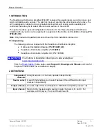
If you use three audio sources and a source select switch, configure the DIP switches as 
shown in Table 3. The Channel C Enable switch must be ON to use the third audio input. 


Table 3  Three audio sources and a select switch 


DIP  

SW1 

DIP 

SW2 

DIP SW6 

Channel C 

Output Channel 

Channel 

OFF 

OFF 

ON 

A, B, & C 

OFF 

ON 

ON 

N/A 

ON 

OFF 

ON 

N/A 

ON 

ON 

ON 

N/A 

4.3. Installation Example 

You can mix the audio control and configure each seat differently, as shown in Figure 3. 

Channels 5 and 6 are set to Input A, and these seats have a choice. Either they may have a 
source select switch to allow them to change their channel, or they can remain without a 
source select switch and stay on input A. 


Figure 3  Configuration DIP switch settings 

           Table 4 DIP switch settings for Figure 3 

Output Channel 

Input Setting 
Fixed Mode 

Input Setting 
Switched Mode


Channel 1 

N/A 

Channel 2 

N/A 

Channel 3 

N/A 

Channel 4 

N/A 

Channel 5 

A, B, C 

Channel 6 

N/A 

Channel 7 

N/A 

Channel 8 

N/A 

Tip:

 For more configuration examples, see the Appendix on page 

11

. 

The N/A outputs do 
not switch the audio 
properly 

Channels 

1

2

, and 

7

 are set to 

Input C

Channels 

3

4

, and 

8

 are set to 

Input B

.  

 
The seats for these six channels do not 
have source select switches.  
 
Only channels 5 and 6, which are set to 
Input A, can use a source select switch. 
This is because the DIP switches 
controlling these channels are turned 
OFF. 

Output 

Ch 1 

Output 

Ch2  

Output 

Ch3  

Output 

Ch4  

Output 

Ch5  

Output 

Ch6  

Output 

Ch7  

Output 

Ch8 

5V Power 

OFF 

Ch C 

ENABLED 

Summary of Contents for 0700-001

Page 1: ...Document Number 100318 Rev A E L E C T R ON I CR E V I S I ON C ON T R OL L E D...

Page 2: ...language in any form by any means without the written authorization from Rosen Aviation LLC except as allowed under copyright laws Disclaimer of Liability The information contained in this document i...

Page 3: ...ATION DIP SWITCHES 5 3 1 Auxiliary Configuration Switches 5 4 CONFIGURING A SINGLE OUTPUT CHANNEL 6 4 1 Fixed Mode Example 6 4 2 Switched Mode Examples 6 4 3 Installation Example 7 5 MOUNTING 8 6 ADJU...

Page 4: ...rained and qualified personnel should perform installation and service 1 1 Unpacking The following parts are shipped with the Headphone Distribution Amplifier Outline and Installation Drawing P N 0700...

Page 5: ...tion DIP switches to set the audio control for all seats Each output channel uses two switches Figure 1 shows the pairs of switches that control each channel Figure 1 The factory default DIP switch se...

Page 6: ...udio source and no select switch DIP SW1 DIP SW2 Input Channel 1 OFF OFF A OFF ON B ON OFF C ON ON N A Channel C control SW6 small bank does not have to be ON to listen to Channel C in fixed mode Note...

Page 7: ...6 are set to Input A and these seats have a choice Either they may have a source select switch to allow them to change their channel or they can remain without a source select switch and stay on inpu...

Page 8: ...level for each input After establishing the maximum audio level use the potentiometers to match the line levels for the audio sources to provide a consistent volume when switching input sources To low...

Page 9: ...8 0 S Curve B Explosive Atmosphere 9 0 N A Waterproofness 10 0 N A Fluids Susceptibility 11 0 N A Sand and Dust 12 0 N A Fungus Resistance 13 0 N A Salt Spray 14 0 N A Magnetic Effect 15 0 A Power Inp...

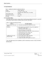
Page 10: ...ubleshooting tips and solutions Problem Possible Solutions Power LED does not illuminate GREEN Verify pinout to power input connection is correct No sound Wait at least five seconds after turning on t...

Page 11: ...o an in flight entertainment system Headphone Distribution Amplifier Seat 1 Seat 2 Seat 3 Seat 4 Channel 4 Pilot Mic Input PA Override In Channel A Channel 1 Channel 2 Channel 3 Channel B Channel C DV...

Page 12: ...l 2 Channel 3 Channel B Channel C SS1 SS2 SS3 SS4 DVD Player Audio Out DVD Player Audio Out DVD Player Audio Out Example 2 The aircraft has four passenger seats Each seat has a headphone jack with a s...

Page 13: ...C SS5 SS6 SS7 SS8 Channel 8 Channel 5 Channel 6 Channel 7 SS5 SS6 SS7 SS8 Example 3 The aircraft has eight passenger seats Seats 1 4 have headphone jacks with no select switch These seats have access...

Reviews: