background image


Document Number 111728 Rev A 


Electronic Revision 

Controlled 

Summary of Contents for 4KS Series

Page 1: ...Document Number 111728 Rev A Electronic Revision Controlled ...

Page 2: ... proprietary to Rosen Aviation LLC No part of this publication may be reproduced transmitted transcribed stored in a retrieval system or translated into any language in any form by any means without the written authorization from Rosen Aviation LLC except as allowed under copyright laws Rosen Aviation LLC 1020 Owen Loop South Eugene OR 97402 541 342 3802 888 668 4955 Fax 541 342 4912 www rosenavia...

Page 3: ...or Bookmark not defined Power Connector J1 Pin out Logic and Function 6 I O J2 Pin out Logic and Function 6 Ethernet Connector J3 Pin out Logic and Function 7 USB J4 Pin out Logic and Function 8 HDMI J5 Pin out Logic and Function 9 Fiber optic J6 Pin out Logic and Function 10 Ethernet Strapping 11 3 6 4K Display Suggested Installation 11 Pre installation 12 Installation 12 4 INITIAL POWER UP 12 4 ...

Page 4: ...on options Each display can be installed in flush mount and semi proud orientations The displays also accommodate a variety of input signals resolutions and control capabilities allowing installation versatility Control Options External IR receiver RS232 Ethernet USB WIFI if equipped Please see interface control document P N 111727 Mating Connectors Recommended mating connectors are listed on the ...

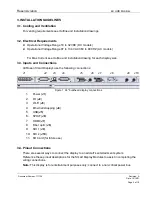
Page 5: ... size 3 3 Inputs and Connections All Rosen Smart Displays use the following connections J1 J2 J3 J4 J5 J6 J7 J8 J9 J10 Figure 1 24 bulkhead display connections 1 Power J1 2 I O J2 3 Wi Fi J3 4 Ethernet strapping J4 5 USB J5 6 SPDIF J6 7 HDMI J7 8 Fiber optic J8 9 SDI 1 J9 10 SDI 2 J10 11 SD Card for future use 3 4 Pinout Connections There are several ways to connect the display to an aircraft s en...

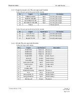
Page 6: ...A1 Line 115 VAC Input Aircraft power supply A2 Earth chassis Input Aircraft power supply A3 Neutral 115 VAC Input Aircraft power supply I O J2 Pin out Logic and Function Table 4 I O Logic and Function Pin Signal Input output Description 1 RESERVED Reserved Reserved 2 RESERVED Reserved Reserved 3 RESERVED Reserved Reserved 4 Signal GND Output Audio line out 5 Audio left Output Audio line out 6 Audi...

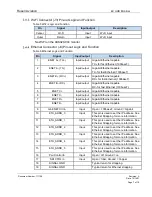
Page 7: ... ENET C Input output Gigabit Ethernet capable 7 ENET D Input output Gigabit Ethernet capable 8 ENET D Input output Gigabit Ethernet capable 9 Gb ENET Ctrl in Input Open 100baseT Ground Gigabit 10 ETH_ADDR_0 Input This pin is used to set the IP address See Ethernet Strapping for more information 11 ETH_ADDR_1 Input This pin is used to set the IP address See Ethernet Strapping for more information 1...

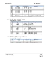
Page 8: ...l use USB J5 Pin out Logic and Function Table 7 USB Logic and Function Pin Signal Input output Description 1 VBUS Output 5 volt Power 2 USB D Input output USB 2 0 Data 3 USB D Input output USB 2 0 Data 4 GND Ground 5 SSRX Input Super speed receiver 6 SSRX Input Super speed receiver 7 GND Ground 8 SSTX Output Super speed Transmitter 9 SSTX Output Super speed Transmitter SPDIF Out J6 Pin out Logic a...

Page 9: ...Data2 Input 2 TMDS Data2 Shield 3 TMDS Data2 Input 4 TMDS Data1 Input 5 TMDS Data1 Shield 6 TMDS Data1 Input 7 TMDS Data0 Input 8 TMDS Data0 Shield 9 TMDS Data0 Input 10 TMDS Clock Input 11 TMDS Clock Shield 12 TMDS Clock Input 13 CEC Input output 14 Reserved 15 SCL Input I C serial clock for DDC 16 SDA Input output I C serial data for DDC 17 Ground Ground 18 5 V Input Power 19 Hot Plug Detect Out...

Page 10: ...put RX for Ethernet 2 4 SDI 2 Input SDI video input 2 5 RESERVED Reserved Reserved 6 RESERVED Reserved Reserved 7 RESERVED Reserved Reserved 8 RESERVED Reserved Reserved 9 RESERVED Reserved Reserved 10 Ethernet 2 TX Output TX for Ethernet 2 11 Reserved Reserved 12 Ethernet 1 TX Output TX for Ethernet 1 SDI Connectors J9 and J10 Pin out Logic and Function Table 11 SDI Logic and Function Pin Signal ...

Page 11: ...ight entries but the addressing range uses all 5 pins for a total of 64 addresses Reference the 4K Display Outline and Installation Drawing for the pin locations in the Ethernet strapping connector Table 12 4K Display Ethernet StrappingIP Address Ethernet Address Pins Logic 5 4 3 2 1 0 10 0 0 100 0 0 0 0 0 0 0 GND 1 OPEN 10 0 0 101 0 0 0 0 0 1 0 GND 1 OPEN 10 0 0 102 0 0 0 0 1 0 0 GND 1 OPEN 10 0 ...

Page 12: ...rs Tooling required for customer supplied aircraft hardware installation For part details see Outline and Installation drawing 3 5 Software upgrade The 4K displays support field upgrade via Ethernet USB which is detailed in P N 110231 or 111727 4 INITIAL POWER UP Make sure that power is turned off and perform the following steps 1 Ensure a low impedance ground connection on the chassis from the gr...

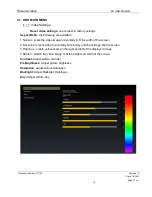
Page 13: ...orizontally to fit the width of the screen 2 Full screen scale video horizontally Vertically until input image fills the screen 3 Pillar box create vertical bars on the right and left of the displayed image 4 Stretch stretch the video image to fit the height and width of the screen Contrast Adjust picture contrast Pix Brightness Adjust picture brightness Saturation Adjust picture Saturation Backli...

Page 14: ...modify how audio is muted from input pin 7 of the J2 connector is used The following are available Ground on Open on or Momentary on Reset all setting This will reset everything to the default mode Video Over scan This is for over scanning of SDI video the default is 25 which is 2 5 Device Alias This allows you to name your device This helps when multiple devices are on the same network Launcher W...

Page 15: ...s can also be transferred via network update contact Rosen Aviation for additional information 5 1 Troubleshooting Table 13 Troubleshooting tips and solutions Problem Possible Solutions Screen is black Verify the unit is receiving power Verify the pinout is correct Verify you are on the correct input Verify the Power Control In signal 5 2 Cleaning the Display If glass surfaces become contaminated ...

Page 16: ...nal Shocks Crash Safety 7 Operational Shocks 7 2 2 B Crash Safety Impulse 7 3 2 B Crash Safety Sustained Fixed Wing Transport Aircraft Random Orientation 9g direction 7 3 3 B Satisfies Inertial Loads requirements per 14 CFR 25 561 b 3 Vibration 8 Random Vibration Fixed Wing Aircraft 8 5 2 S Curve B Waterproofness 10 Y Substantiation by Company Testing Fluids Susceptibility 11 Fluids Spray Coffee O...

Page 17: ... Susceptibility 19 Magnetic Fields Induced Into Equipment 19 3 1 AC Electric Fields Induced into Equipment 19 3 2 Not applicable to equipment with metal enclosure Magnetic Fields Induced Into Interconnecting Cables 19 3 3 AC Electric Fields Induced Into Interconnecting Cables 19 3 4 AC Spikes Induced Into Interconnecting Cables 19 3 5 AC Radio Frequency Susceptibility 20 Conducted Susceptibility C...

Page 18: ...solutions 3840x2160 23 97 3840x2160 24 3840x2160 25 3840x2160 29 97 3840x2160 30 3840x2160 50 3840x2160 59 94 3840x2160 60 HDMI resolutions 480i 29 97 480i 30 576i 25 480p 59 94 480p 60 576p 50 720p 50 720p 59 94 720p 60 1080i 25 1080i 29 97 1080i 30 1080p 23 97 1080p 24 1080p 25 1080p 29 97 1080p 30 1080p 50 1080p 59 94 1080p 60 3840x2160 23 97 3840x2160 24 3840x2160 25 3840x2160 29 97 3840x2160 ...

Page 19: ... single 2 970 Gbit s serial link LRU Line Replaceable Unit LCD Liquid Crystal Display P N Part Number RS 232 Standard for serial data communication lines VDC Volts direct current 7 REVISION HISTORY Revision E is limited to draft or prototype documents Revisions I O Q S X and Z are not to be used Revision Date Revision Description EC A 10 14 21 Initial release 21 0472 ...

Reviews: