background image

CASE 

6A Series

USER Manual

www.rosewill.com

Summary of Contents for CASE 6A Series

Page 1: ...CASE 6A Series USER Manual www rosewill com...

Page 2: ...guration Features Descriptions Installation 1 Opening Chassis 2 Installing Motherboard 3 Installing Power Supply 4 Installing 5 25 Device 5 Installing 3 5 Floppy 6 Installing 3 5 HDD 7 Installing Add...

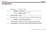
Page 3: ...Slots Thermal Solution Air Filter I O Port Bracket Megal Material 8 3 x 18 1 x 16 9 ATX Micro ATX External 4 x 5 25 2 x 3 5 Internal 5 x 3 5 7 Slots 1 x 120 mm fan in rear and 1 x 120 mm fan holder in...

Page 4: ...ts reserved by Rosewill Features Descriptions Rear 120mm Fan Front 120mm Fan Holder Sliding Rails for 5 25 Device Vertical sliding HDD cage HDD cage with Shockproof Rubber Pads Add on Card Kit No Scre...

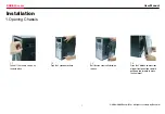
Page 5: ...ll 1 2 Push the 2 side door buttons 1 4 Press the 2 buttons on both sides of lower front panel and carefully pull down and forward to move the front panel Installation 1 Opening Chassis 1 1 Take off t...

Page 6: ...ed by Rosewill 2 1 Locate and align the screw holes on the motherboard and chasis place the motherboard at the correct position and then screw brass studs onto chasis s metal shell 2 2 Secure the moth...

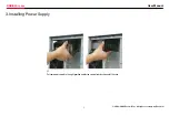
Page 7: ...ASE 6A series User Manual 2004 2006 Rosewill Inc All rights reserved by Rosewill 3 1 Put your power supply in the right position and fasten screws from back panel of the case 3 Installing Power Supply...

Page 8: ...as CD ROM and screw the rails onto the 5 25 device 4 2 Insert the railed device into the 5 25 drive bay 4 Installing 5 25 Device PS Recommend to remove the 5 25 metal cover below the bay you want to i...

Page 9: ...will 5 Installing 3 5 Floppy 5 2 Slide the floppy or if necessary HDD into the drive bay 5 4 Slide the small cage into drive bay make sure the cate is properly positioned 5 1 Pull the handle and cage...

Page 10: ...the handle down and pull the large cage out 6 4 Screw up and fasten HDD on the cage Handle with care because HDD is likely to be damaged by careless management 6 1 Take off the thumb screw on the larg...

Page 11: ...served by Rosewill 7 Installing Add on Card 7 3 Push down the kit to fasten the add on card 7 1 Loosen the kit above the slot you want to install your add on card in and remove the metal cover by your...

Page 12: ...he various interfaces Most frequently there will be a picture of the pins with which the cable is attached The number of pins on your motherboard might not always equal the number of connectors on the...

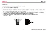
Page 13: ...tly there will be a picture of the pins with which the cable is attached 2 Each pin is defined very strictly Please pay attention to the figures below which helps install the audio cable fast safely a...

Page 14: ...lity Rosewill Product Please register your product at www rosewill com for complete warranty information and future support for your product If you have any question while using our products please fe...

Reviews: