Full Motion Dual Arm, Tilt TV Mount
RHTB-11014FT User Manual
English
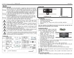
Warning Statements
Warning
The wall structure must be capable of supporting at least a maximum weight of
60kg (132lbs) for 37”-60” televisions and 56kg (123lbs) for 25”-37” televisions.
If not, the wall must be reinforced. Proper installation procedure by a qualified
service technician, as outlined in the installation instructions, must be adhered
to. Failure to do so could result in serious personal injury, or even death.
Warning
Safety measures must be practiced at all times during the installation of this
product. Use proper safety gear and tools for the installation procedure to
prevent personal injury.
Warning
Prior to the installation of this product, the installation instructions should be
read and completely understood. The installation instructions must be read to
prevent personal injury and property damage. Keep these installation
instructions in an easily accessible location for future reference.
A secure structure must support the weight or load of the display, When
mounting to a wall that contains wooden studs, dead center of the wooden
stud must be confirmed prior to installation.
Do not install on a structure that is prone to vibration, movement or chance of
impact. Failure to do so could result in damage to the display and/or damage
to the mounting surface.
Do not install near heater, fireplace, direct sunlight, air conditioning or any
other source of direct heat energy. Failure to do so may result in damage to
the display and could increase the risk of fire.
At least two qualified people should perform the installation procedure. Injury
and/or damage can result from dropping or mishandling the display.
Recommended mounting surfaces: wooden studs and solid-flat concrete. If the
mount is to be installed on any surface other than wooden studs, use suitable
hardware (which is commercially available).
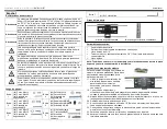
Hardware kit:
Bag
1
(x4) M4x12 Bolt
(x4) M4x30 Bolt
(x4) M4 Lock Washer
Bag
4
(x4) M8x16 Bolt
(x4) M8x40 Bolt
(x4) M8 Lock
Washer
Bag
2
(x4) M5x12 Bolt
(x4) M5x30 Bolt
(x4) M5 Lock
Washer
Bag
5
(x4) M4/M5 Spacer
(x4) M6/M8 Spacer
(x4) M4/M5 Washe
Bag
3
(x4) M6x12 Bolt
(x4) M6x35 Bolt
(x4) M6 Lock
Washer
Bag
6
(x1) Bubble Level System
(x6) M8x60 Lag Bolt
(x6) Washer
(x6) Concret anchor
Bag 7
(x1) S=3 Allen Wrench
Product Parts
A. Wall Plate x1pc B. TV Brackets x2pcs
Tools Required:
Phillips Head Screw driver
Stud finder for drywall installation
5/16” Socket and Wrench
Electric drill and 3/8” (10mm) masonry bit for concrete/brick installation
Spanner
Note: You need to put the bubble level system on the pipe when you install the wall
plate and take it away after you finish installation.
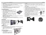
Wood Stud Installation
For secure wood stud mounting, the wall plate
must be mounted to two studs at least 12” apart.
1. Use a high-quality electronic stud finder
(commercially available) to locate two
adjacent studs and mark their
locations with a pencil.
2. With the help of an assistant, and
using the bubble level to ensure the
wall plate is level, position the wall
plate against the wall in the desired
mounting location.
3. Mark the right, upper and lower and the left (upper and lower), positions of the small
horizontal slots that are in alignment with the studs.
4. You should mark four positions total.
5. Next, pre-drill a 1/5”(5mm) hole in the wall stud at each marked location.
6. With the help of an assistant, position the wall plate against the wall and line up the
mounting slots with drilled holes.
7. For each location, insert a lag bolt and washer into the wall.
8. Tighten bolt with an open ended socket wrench by turning clockwise until tight.
CAUTION:
Do not over-tighten bolts-doing so may cause unnecessary damage to the wall.
Avoid excessive torque.
CAUTION:
Do not release the wall plate until it is properly mounted and secured to the
wall.
Concrete/Brick Installation
1. Begin by placing the wall plate into position against the wall, using the bubble level to


